Duct system for profiled post-tension construction

a technology of duct system and post-tension construction, which is applied in the field of ducts, can solve the problems of weak structural concrete, inability to carry significant tensile loads, and inability to use the full potentiality of concrete, and achieves the effect of reducing the difficulty of duct use in association with profiled load-balancing tendons

Active Publication Date: 2009-11-24
SORKIN FELIX L
View PDF17 Cites 24 Cited by
  • Summary
  • Abstract
  • Description
  • Claims
  • Application Information

AI Technical Summary

Benefits of technology

[0031]The present invention is a duct system for profiled post-tendon construction comprising a first duct of a first polymeric material, a second duct of a second polymeric material and a third duct of a third p

Problems solved by technology

On the other hand, structural concrete, though quite capable of carrying almost any compressive load, is weak in carrying significant tensile loads.
Structures of reinforced concrete may be constructed with load-bearing walls, but this method does not use the full potentialities of the concrete.
With all of these polymeric duct constructions, the use of such ducts in association with profiled load-balancing tendons has been somewhat difficult.
However, when tendons are profiled by using the load-balancing technique, a curvature in the tendon will occur.
Under the enormous tension loads that applied to the tendon, the contact between the tendons and the inner wall of such ducts can potentially impair the integrity of the duct system.
Unfortunately,

Method used


Image

  • Duct system for profiled post-tension construction
  • Duct system for profiled post-tension construction
  • Duct system for profiled post-tension construction

Examples


Embodiment Construction

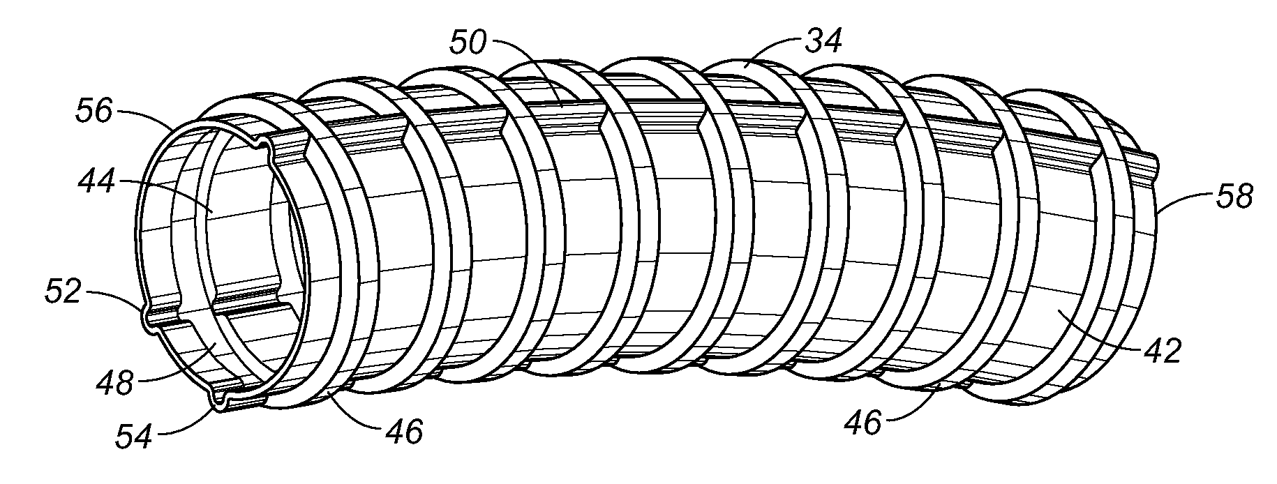
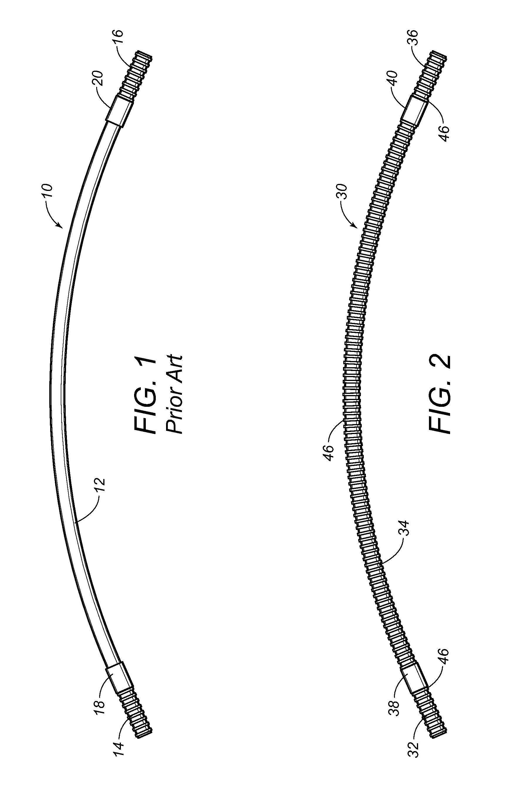
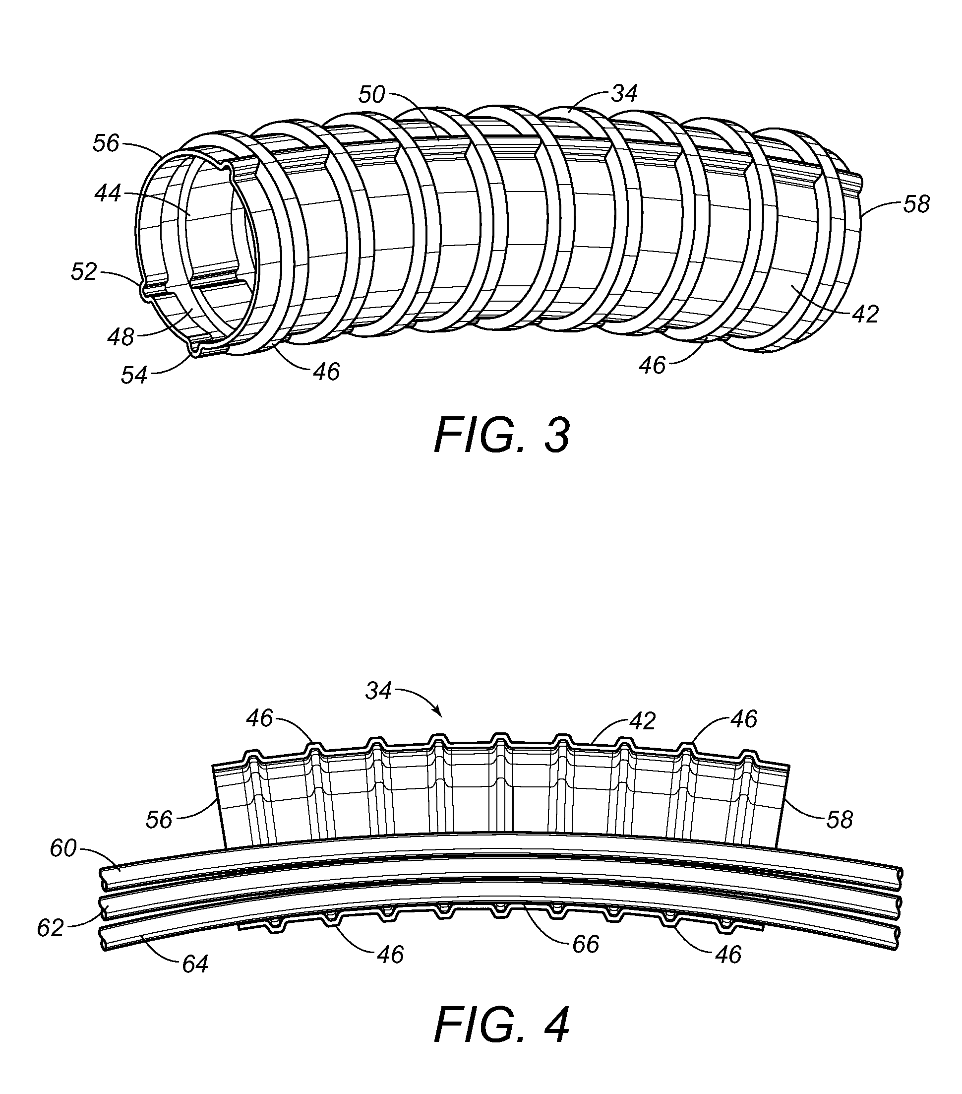
[0040]Referring to FIG. 2, there is shown the duct system 30 in accordance with the preferred embodiment of the present invention. The duct system 30 includes a first duct 32, a second duct 34, and a third duct 36. The first duct 32 is of a first polymeric material. The second duct 34 is of a second polymeric material. The third duct 36 is of a third polymeric material. The polymeric material used for the second duct 34 is more wear resistant than the polymeric materials used for the first duct 32 or the third duct 36. As can be seen, a coupler 38 is used to join one end of the second duct 34 to an end of the first duct 32. A second coupler 40 is used to join the opposite end of the second duct 34 to an end of the third duct 36. Couplers 38 and 40 can have a variety of configuration including, but not limited to, the configuration of couplers described in U.S. Pat. Nos. 5,474,335, 5,775,849 and 5,954,373 to the present inventor.

[0041]It is important to note that, with respect to the...


PUM


Abstract

A duct system for profiled post-tendon construction has a first duct, a second duct and a third duct joined together in end-to-end relationship. The first and third ducts are of one type of polymeric material. The second duct is of a different type of polymeric material. The second duct has a parabolic curvature while the first and third ducts are generally straight. The second duct has a cross-sectional configuration that is identical to the cross-sectional configuration of the first and third ducts.

Description

RELATED U.S. APPLICATIONS[0001]Not applicable.STATEMENT REGARDING FEDERALLY SPONSORED RESEARCH OR DEVELOPMENT[0002]Not applicable.REFERENCE TO MICROFICHE APPENDIX[0003]Not applicable.FIELD OF THE INVENTION[0004]The present invention relates to ducts as used in post-tension construction. More particularly, the present invention relates to ducts that are used for receiving tendons in a multi-strand tensioning system in an encapsulated environment. Additionally, the present invention relates to ducts as used for load balancing and for profiled post-tension construction.BACKGROUND OF THE INVENTION[0005]For many years, the design of concrete structures imitated the typical steel design of column, girder and beam. With technological advances in structural concrete, however, its own form began to evolve. Concrete has the advantages of lower cost than steel, of not requiring fireproofing, and of its plasticity, a quality that lends itself to free flowing or boldly massive architectural conc...

Claims


Application Information

Patent Timeline
IPC IPC(8): E04C5/08
CPCE04C5/10
Inventor SORKIN, FELIX L.
Owner SORKIN FELIX L
Why Eureka
Try Eureka