

Slide lock
a technology of sliding lock and sliding plate, which is applied in the field of static progressive splinting, can solve the problems of heavy, bulky or cumbersome, and affecting so as to reduce the overall size of the splint for a patient, prevent the device from catching on a patient's clothes, and reduce the overall size of the splin
- Summary
- Abstract
- Description
- Claims
- Application Information
AI Technical Summary
Benefits of technology
Problems solved by technology
Method used
Image

Examples
Embodiment Construction
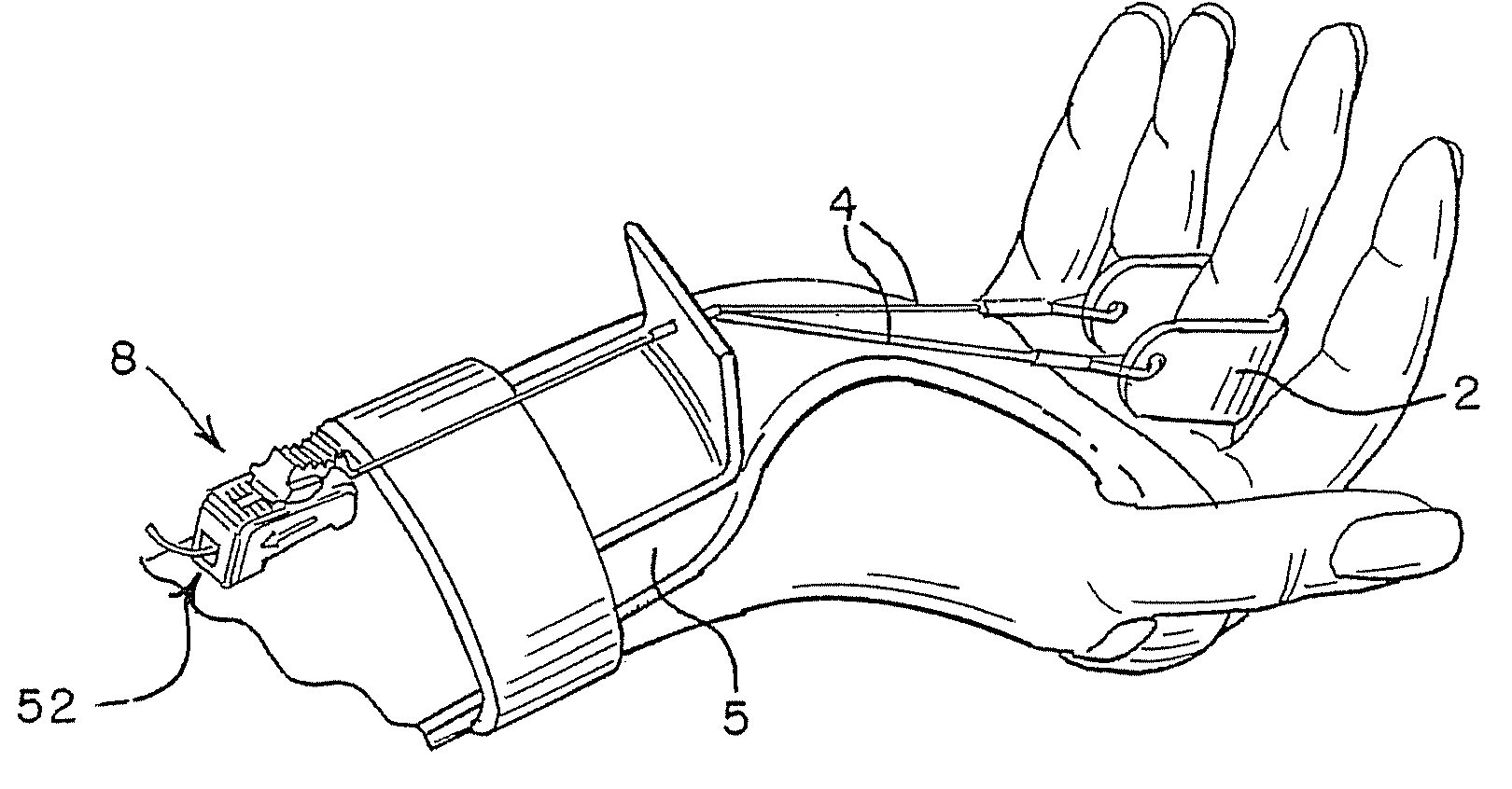
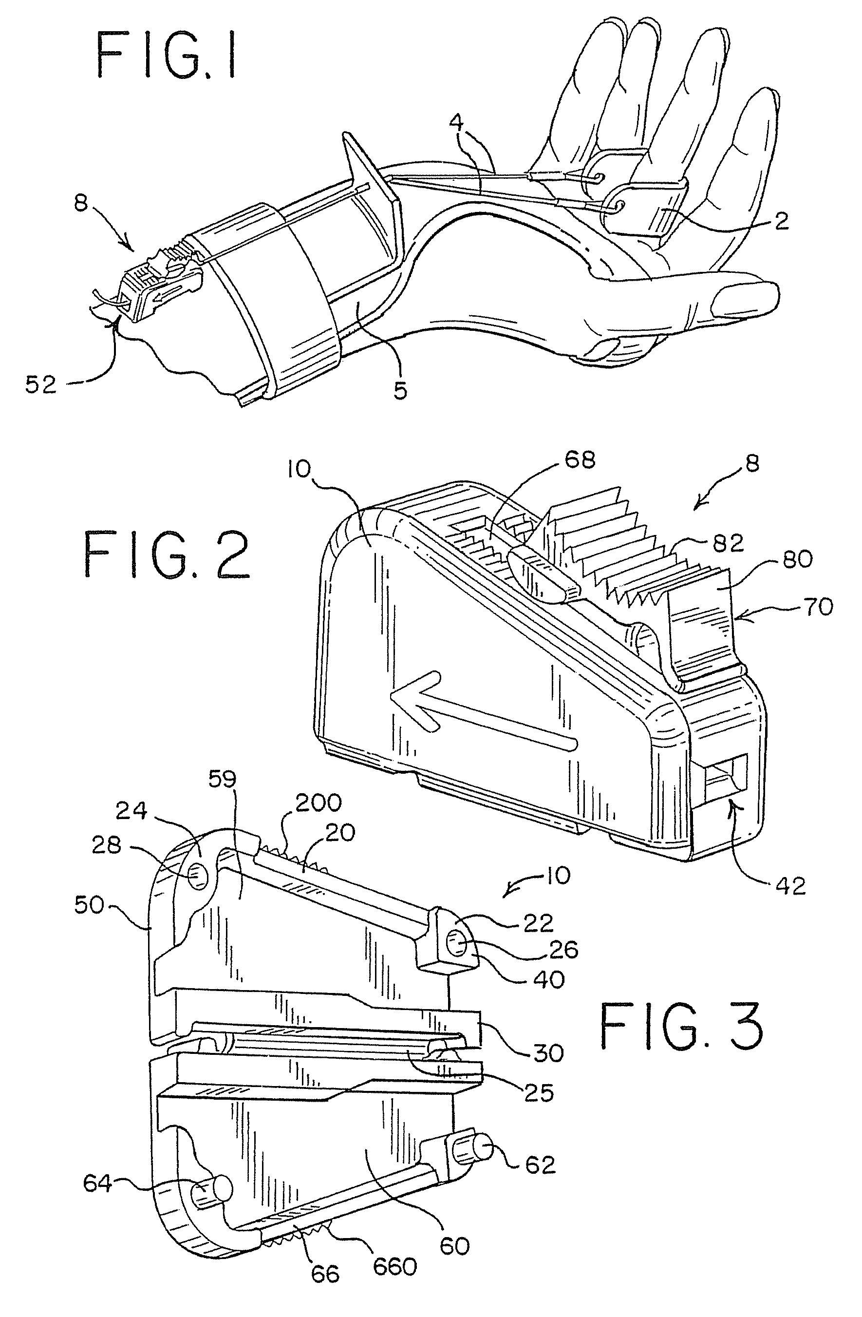
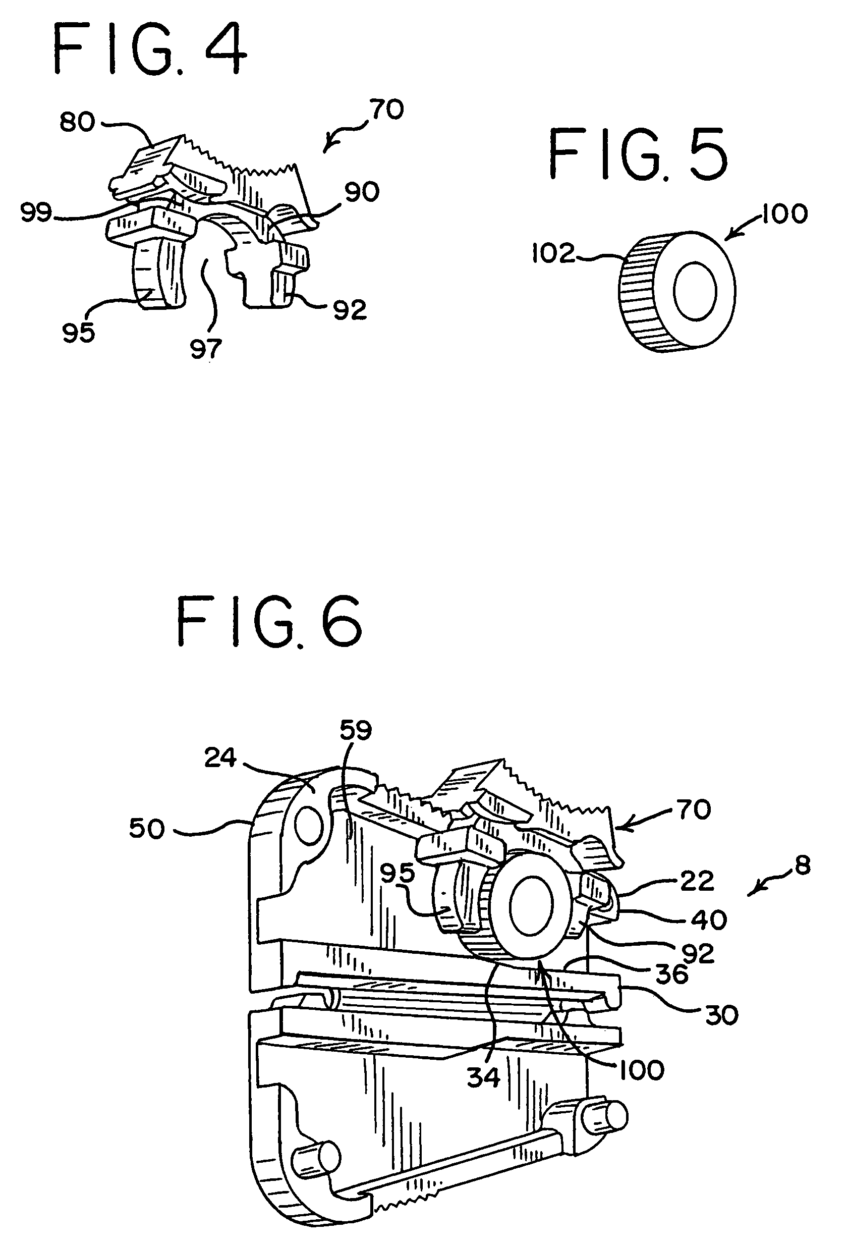
[0016]A monofilament slide lock made in accordance with the principles of the present invention is depicted in FIGS. 2-6. The present invention is to be used in a static progressive splinting system such as the one shown in FIG. 1. The system 1 includes a sling 2, a plurality of monofilaments 4, a splint 5, and a monofilament slide lock 8 for securing the tension of the monofilaments 4. The slide lock 8 of the present invention generally comprises a housing 10, a glide member 70, and a locking wheel 100.
[0017]As shown in FIG. 3, the housing 10 has an upper ridge 20 and a lower ridge 30 positioned on a first sidewall 59. The upper ridge 20 extends from the rear surface 50 of the first sidewall 59 to the front surface 40 and terminates at each end at a column 22, 24. A second sidewall 60 has an upper ridge 66 and two posts 62, 64. Both upper ridges 20, 66 are preferably equipped with a textured outer surface 200, 660, and the second sidewall 60 is preferably linked to the lower ridge ...
PUM
 Abstract
Description
Claims
Application Information