MRI apparatus and method using sample filtering based on time shifts caused by temporal variations in magnetic field strength

a temporal variation and magnetic field technology, applied in the field of mri apparatus, can solve problems such as deteriorating real-time image data quality, difficulty in practice to obtain magnetic field, and image distortion caused by mr signal frequency variations

Inactive Publication Date: 2009-12-01
TOSHIBA MEDICAL SYST CORP
View PDF5 Cites 44 Cited by
  • Summary
  • Abstract
  • Description
  • Claims
  • Application Information

AI Technical Summary

Problems solved by technology

However, it is difficult in practice to obtain a magnetic field in which activation time is short and strength is substantially uniform during the readout period, such as a magnetic-field characteristic with rectangle or trapezoid shape, due to constraints, such as a limitation of a gradient magnetic field power-source or the like, consequently, a sinusoidal-shaped readout gradient magnetic field is used in many cases.
As a result, when creating image data by performing the A / D conversion and then the reconstruction processing on the MR signal collected in the readout encoding direction, an image distortion caused by the variations in the frequency of the MR signal arises in the image data obtained by performing a Fourier transform on the MR signal obtained by sampling at an equal interval.
In other words, because the filtering processing for eliminating a needless signal is performed on the MR signal of which MR-signal frequency is corrected, such processing requires a number of periods, consequently, the method has a problem that a real-time quality of image data is deteriorated.

Method used


Image

  • MRI apparatus and method using sample filtering based on time shifts caused by temporal variations in magnetic field strength
  • MRI apparatus and method using sample filtering based on time shifts caused by temporal variations in magnetic field strength
  • MRI apparatus and method using sample filtering based on time shifts caused by temporal variations in magnetic field strength

Examples


Embodiment Construction

[0025]Exemplary embodiments of the present invention will be explained below with reference to the accompanying drawings.

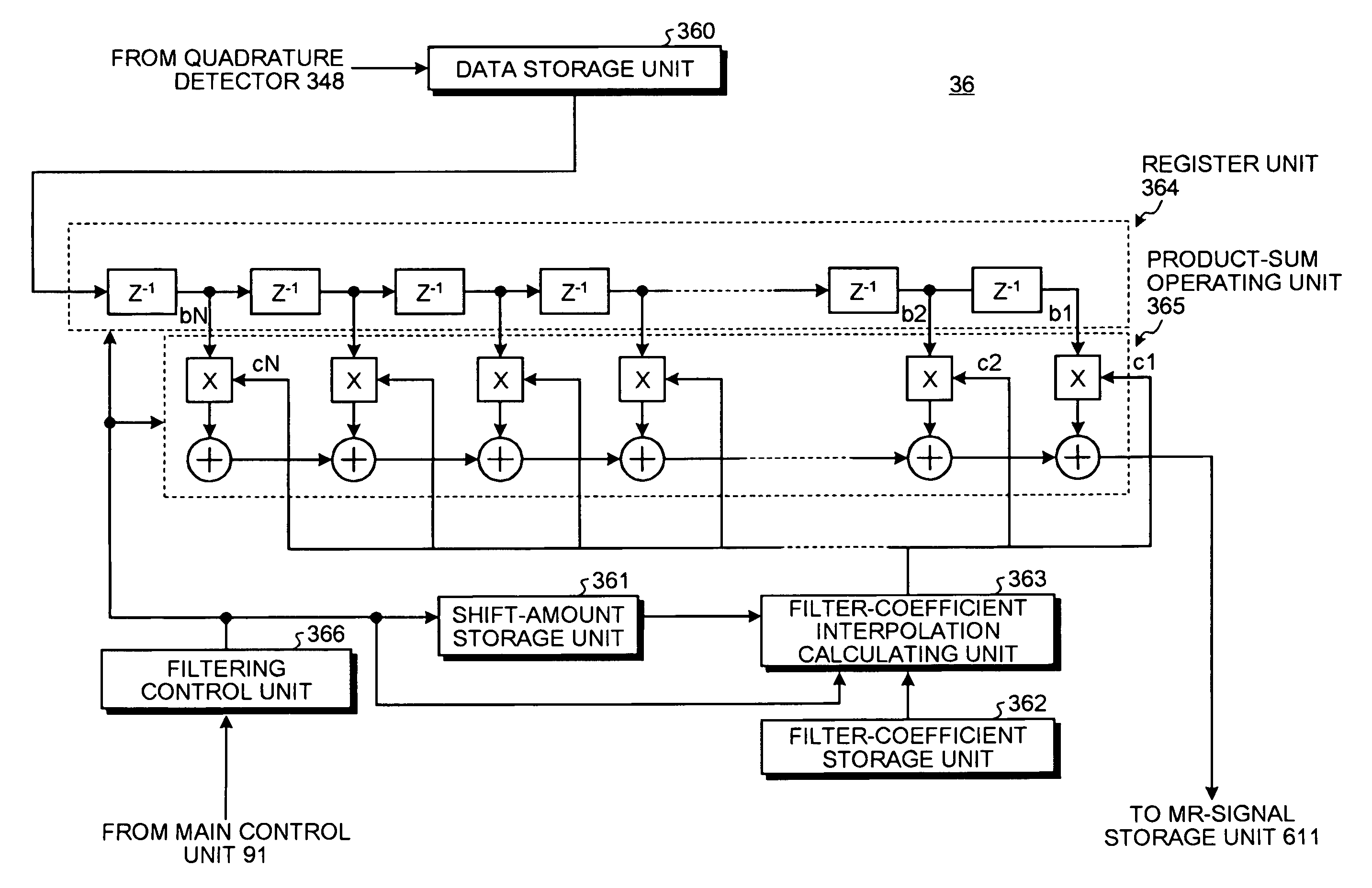
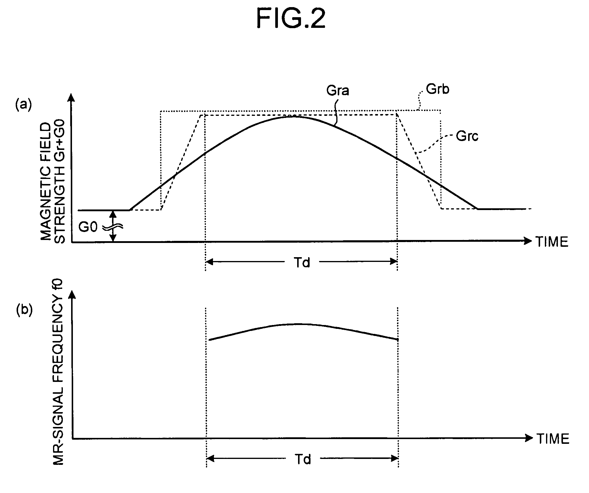
[0026]In the following embodiment of the present invention, when eliminating with a digital filter various noise components superimposed on an MR signal after quadrature detection collected at a predetermined sampling interval, resampling time corresponding to the signal band of the MR signal is set for the MR signal sampled at sampling time with the predetermined interval, and furthermore, the resampling time is corrected based on magnetic-field characteristic of readout gradient magnetic field that varies with time. Discrete standard filter-coefficients preset at the sampling interval are then interpolated, filter coefficients of a filter function with a center on one of the corrected resampling time are calculated with respect to respective points of the sampling time, and MR-signal amplitude values at the corrected resampling time are calculated by convolution...


PUM


Abstract

An MRI apparatus includes a filtering control unit that filters discrete MR-signal values. A filter-coefficient setting unit sets a plurality of filter coefficients with respect to each point of sampling time, based on time-shift amounts corresponding to variations in an MR-signal frequency arising from temporal variations in the magnetic field strength. A product-sum operating unit filters the MR-signal values by performing a product-sum operation between the filter coefficients and the MR-signal values. An image-data creating unit creates image data based on the MR-signal values on which the filtering processing is performed.

Description

CROSS-REFERENCE TO RELATED APPLICATIONS[0001]This application is based upon and claims the benefit of priority from the prior Japanese Patent Application No. 2007-099243, filed on Apr. 5, 2007; the entire contents of which are incorporated herein by reference.BACKGROUND OF THE INVENTION[0002]1. Field of the Invention[0003]The present invention relates to an MRI apparatus, and particularly relates to an MRI apparatus that can correct variations in an MR-signal frequency caused by temporal variations in a readout gradient magnetic field.[0004]2. Description of the Related Art[0005]A magnetic resonance imaging (MRI) method is an imaging method in which a nuclear spin in a subject tissue placed in a static magnetic field is excited with a high-frequency signal (RF pulse) of a Larmor frequency, and image data is reconstructed from a magnetic resonance signal (MR signs)) generated along with the excitation.[0006]An MRI apparatus is a diagnostic imaging apparatus that creates image data ba...

Claims


Application Information

Patent Timeline
Patent Type & Authority Patents(United States)
IPC IPC(8): G01V3/00
CPCG01R33/56572
Inventor ADACHI, KOHEI
Owner TOSHIBA MEDICAL SYST CORP
Why Eureka
Try Eureka