Apparatus for a wire wrapping process

a technology of wire wrapping and apparatus, applied in the field of apparatus and a wire wrapping process, can solve the problems of unduly cumbersome process, time-consuming, repair or scrapping, etc., and achieve the effect of simple and economical use of the mounting apparatus

Inactive Publication Date: 2009-12-15
HONG FU JIN PRECISION IND (SHENZHEN) CO LTD +1
View PDF15 Cites 0 Cited by
  • Summary
  • Abstract
  • Description
  • Claims
  • Application Information

AI Technical Summary

Benefits of technology

[0009]It is simple and economical to use the mounting apparatus for holding a connector during wire wrapping process.

Problems solved by technology

If, on the other hand, the PCA fails the test, it may either be repaired or scrapped.
The process is unduly cumbersome and time consuming.

Method used


Image

  • Apparatus for a wire wrapping process
  • Apparatus for a wire wrapping process
  • Apparatus for a wire wrapping process

Examples


Embodiment Construction

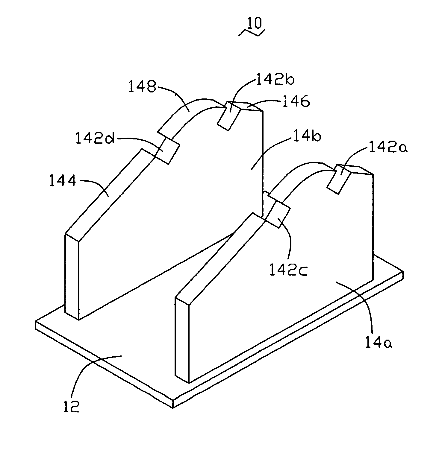
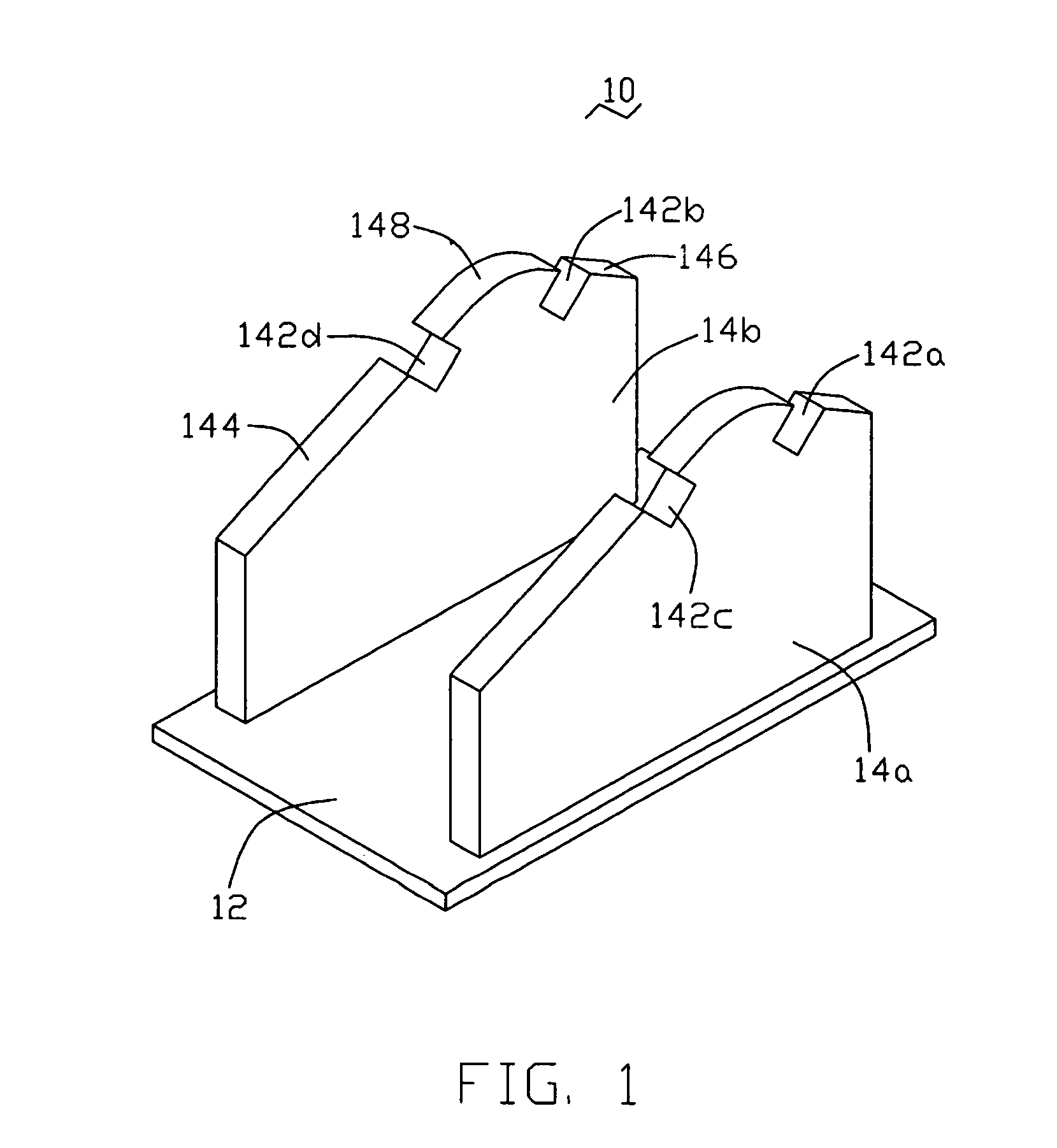
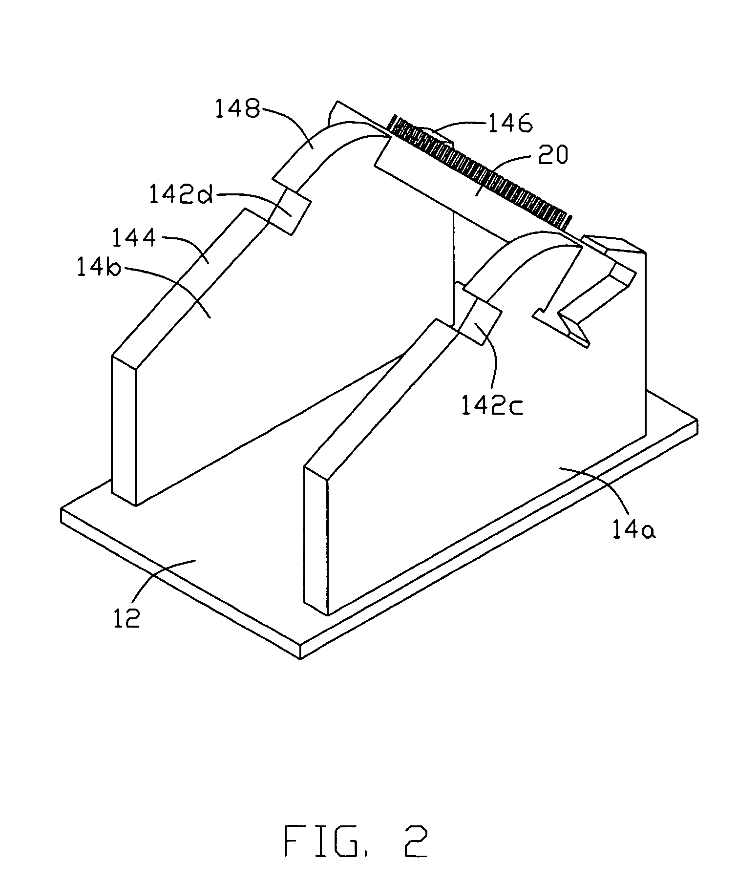
[0013]Referring to FIG. 1 and FIG. 2, a mounting apparatus 10 for holding connectors during a wire wrapping process, includes a base 12, and two shoe plates 14a and 14b formed on a top surface of the base 12. The shoe plates 14a and 14b are standing parallel with each other. A top of each shoe plate includes a first slanting surface 144, a second slanting surface 146, and an arc-shaped surface 148 connecting the first slanting surface 144 and the second slanting surface 146. The shoe plates 14a and 14b define corresponding U-shaped grooves 142a and 142b respectively between the second slanting surface 146 and the arc-shaped surface 148 thereof for holding a connector 20 which is used to connect PCA test equipment with test pins. The interval between the shoe plates 14a and 14b is less than the length of the connector 20.

[0014]The shoe plates 14a and 14b further define corresponding U-shaped grooves 142c and 142d respectively between the first slanting surface 144 and the arc-shaped ...


PUM

PropertyMeasurementUnit
lengthaaaaaaaaaa
distanceaaaaaaaaaa
timeaaaaaaaaaa

Abstract

A mounting apparatus includes a base and at least one pair of shoe plates. The shoe plates are formed on a top surface of the base. Each of the shoe plates comprises a plurality of grooves respectively on top surfaces thereof for holding at least one connector. It is simple and economical to using the mounting apparatus for holding a connector during a wire wrapping process.

Description

BACKGROUND OF THE INVENTION[0001]1. Field of the Invention[0002]The present invention relates to an apparatus and a method for a wire wrapping process.[0003]2. General Background[0004]In-circuit test (ICT) is typically used to test printed circuit assemblies (PCA) to ensure the proper functioning and operation thereof. If the printed circuit assembly or PCB successfully passes the test, it may be passed on for incorporation into the appropriate sub-assembly or into the final product. If, on the other hand, the PCA fails the test, it may either be repaired or scrapped.[0005]One type of ICT probe that is commonly used today includes a two dimensional grid or array of elongated, spring-loaded test pins or “pogo pins.” The test pins or pogo pins may be arranged on a supporting board or substrate so that the pins extend generally outward from the surface of the board. The arrangement of the test pins on the board is similar to a so-called “bed of nails” and such ICT probes are often refe...

Claims


Application Information

Patent Timeline
Patent Type & Authority Patents(United States)
IPC IPC(8): H01R43/00
CPCH01R43/033Y10T29/49174Y10T29/5151Y10T29/53213Y10T29/53226
Inventor LI, HAIZHAN, YOU-HUI
Owner HONG FU JIN PRECISION IND (SHENZHEN) CO LTD
Why Eureka
Try Eureka