Roofing product possessing thermal expansion relief characteristics

a technology of thermal expansion relief and roof covering, which is applied in the direction of roofs, constructions, building components, etc., can solve the problems of reducing the aesthetics of roof products, moving out of the engagement with roof decks, etc., and achieves the effect of improving roof system performance and reducing stress loads

Inactive Publication Date: 2009-12-15
TAMKO BUILDING PRODS
View PDF30 Cites 11 Cited by
  • Summary
  • Abstract
  • Description
  • Claims
  • Application Information

AI Technical Summary

Benefits of technology

[0008]Improved roofing system performance is achieved through a roofing member or shingle possessing thermal expansion relief characteristics. In one aspect, the roofing member provides thermal expansion relief when mounted adjacent to other roofing members in laterally extending courses on a roof surface. Specifically, each roofing member has a main body with top and bottom surfaces, and side regions, as well as one or more spacer tabs extending outwardly from one or more of the side regions. Each spacer tabs extends outwardly from a location on one of the side regions that is adjacent to one of a set of depressions formed into the bottom surface of the main body. In this way, when thermal expansion of adjacently mounted roofing members occurs causing a compressive force to be applied against particular spacer tabs, the particular spacer tabs fail in a way that at least partially displaces the respective spacer tabs into the adjacently positioned depressions, thereby reducing the stress loads that adjacent shingles apply to one another.
[0010]The invention of another aspect takes the form a roofing member having a main body, a cutout feature, and a spacer tab feature. Specifically, the main body includes top and bottom surfaces, and side regions, with the cutout feature formed into one or more of the side regions and spacer tab feature extending outwardly from at least one of the side regions proximal to the respective cutout feature. In this way, when thermal expansion of adjacently mounted roofing members occurs causing a compressive force to be applied against the spacer tab feature inwardly with respect to one or more of the side regions, the cutout feature and the spacer tab feature cooperatively provide stress relief through movement of the spacer tab feature at least partially into the cutout feature.

Problems solved by technology

One particular problem faced by shingle installers is how to account for thermal expansion and contraction cycles that occur when singles are exposed to temperature extremes in the outdoor environment.
This is especially problematic when a semi-rigid to rigid shingle has fixed point of attachment on a building roof structure and will become exposed to temperatures that vary greatly from the temperature of the shingle when it is installed on the roof, such a temperature differential being referred to herein as “Delta T”.
This bowing effect can undermine the attachment of the fasteners extending through the nailing zones 102, potentially causing them to move out of engagement with the roof deck.
Furthermore, the bowing diminishes the aesthetics of the roofing product.

Method used


Image

  • Roofing product possessing thermal expansion relief characteristics
  • Roofing product possessing thermal expansion relief characteristics
  • Roofing product possessing thermal expansion relief characteristics

Examples


Embodiment Construction

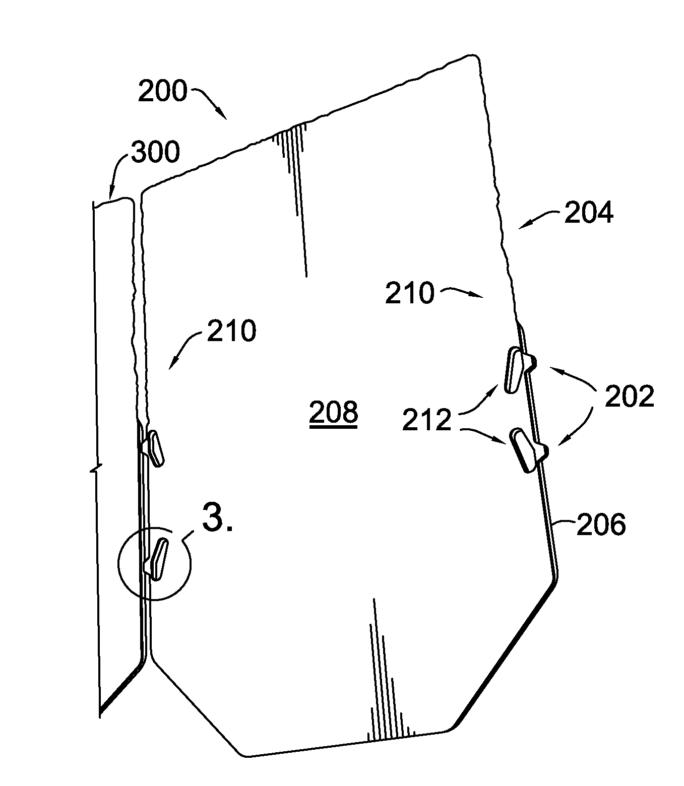
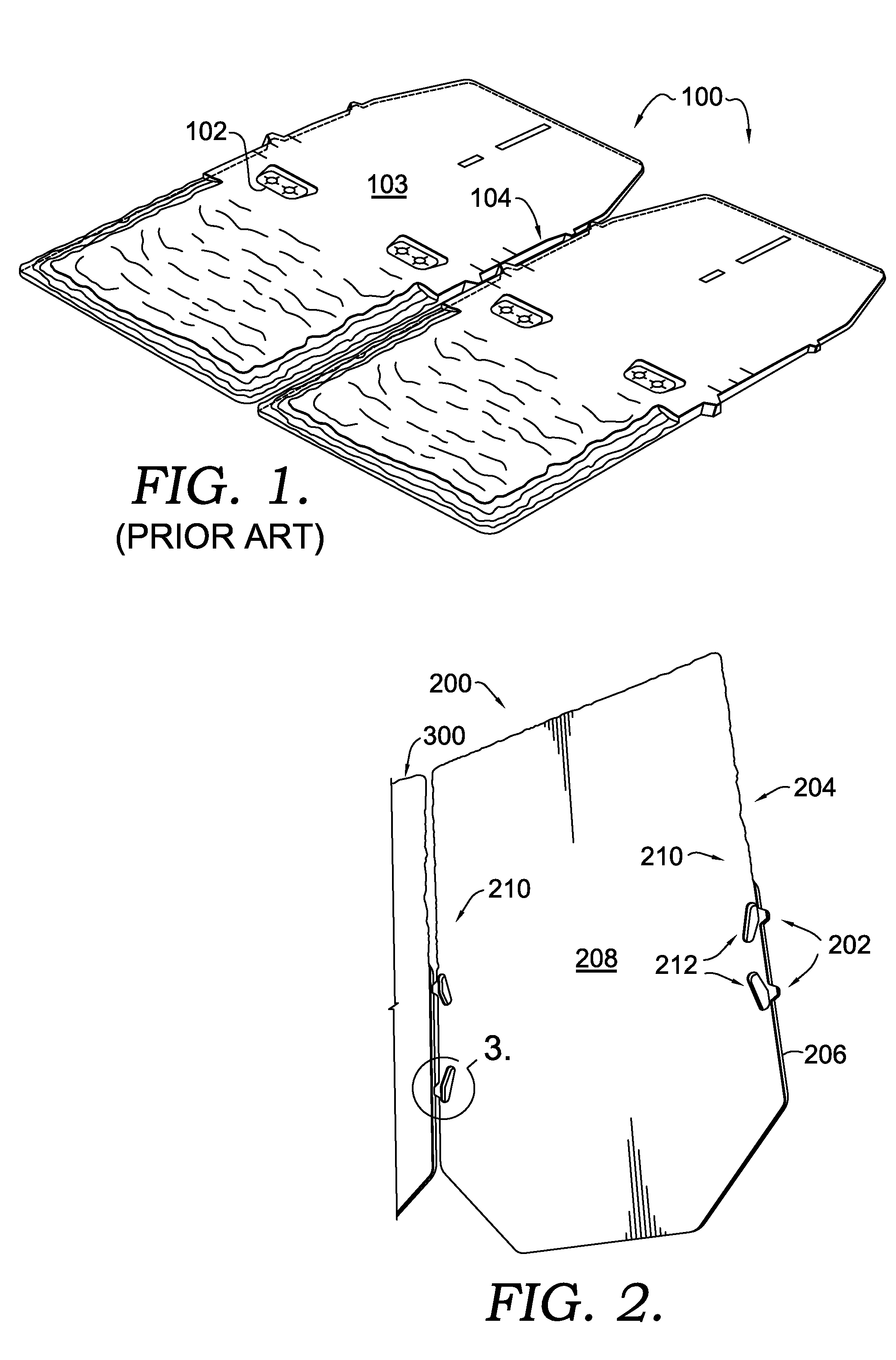
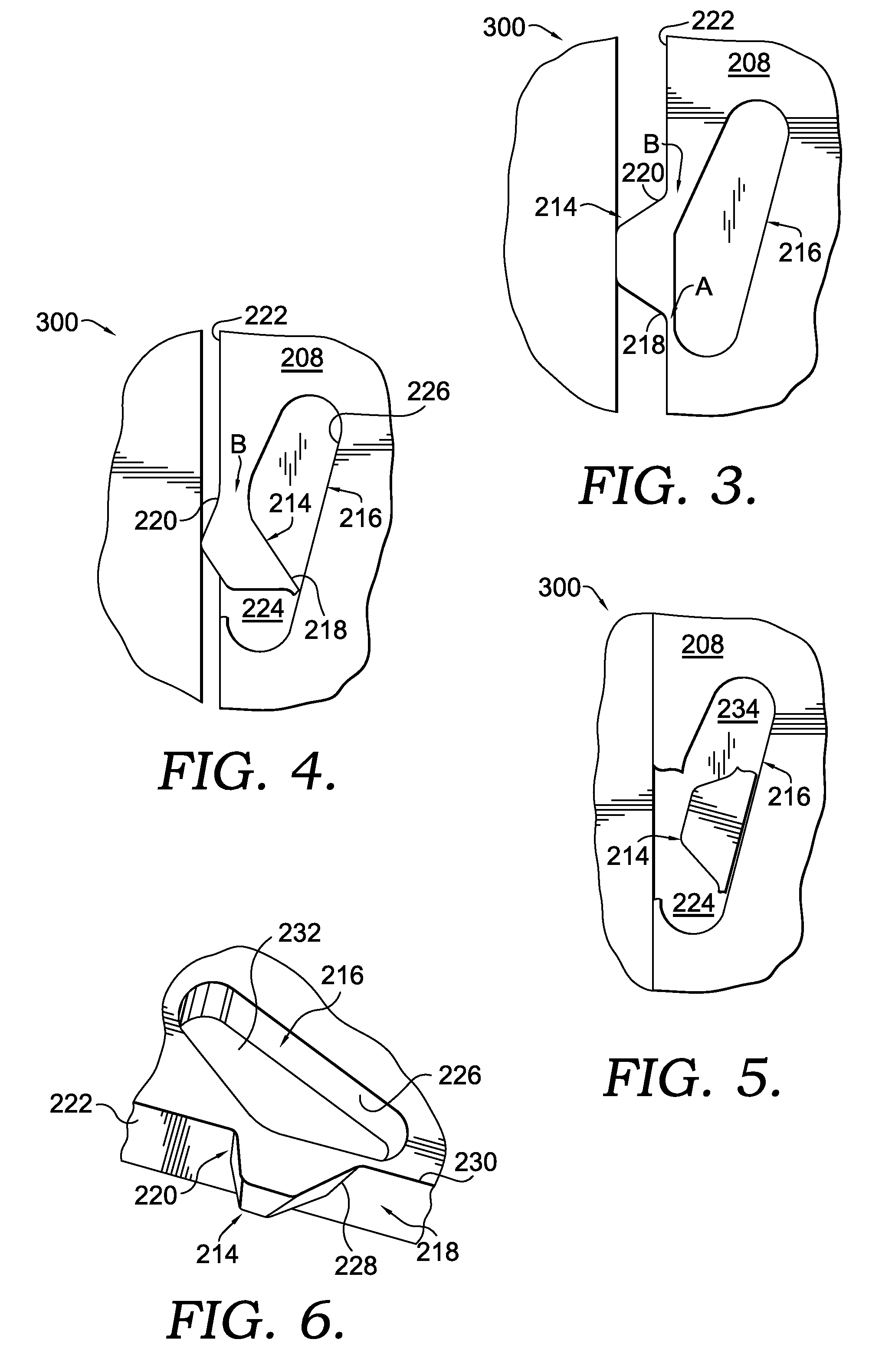
[0022]The present invention provides a roofing system formed by roofing members or shingles possessing thermal expansion relief characteristics. The roofing system provides a degree of “play” between adjacently mounted shingles on a roof structure. Specifically, as the shingles expand in size due to the temperature of the shingles becoming elevated, spacer tabs which are typically utilized to properly align and space apart shingles for installation are allowed to be displaced inwardly into the side regions of the shingles. This allows the side regions of the shingles to avoid the high compressive loads applied by thermally expanding adjacent shingles. In certain embodiments, the spacer tabs are configured to substantially only undergo elastic deformation when thermal expansion occurs, while in other embodiments, certain modes of failure result in the spacer tabs partially or fully breaking away from connection with the side regions of the respective shingle.

[0023]Turning to FIGS. 2-...


PUM

PropertyMeasurementUnit
thermal expansionaaaaaaaaaa
compressive forceaaaaaaaaaa
thicknessaaaaaaaaaa

Abstract

A roofing member provides improved thermal expansion relief characteristics when mounted adjacent to other roofing members in laterally extending courses on a roof surface. According to one arrangement, the roofing member has a main body with top and bottom surfaces, and side regions, as well as one or more spacer tabs extending outwardly from one or more of the side regions. Each spacer tab extends outwardly from a location on one of the side regions that is adjacent to one of a set of depressions formed into the bottom surface of the main body. In this way, when thermal expansion of adjacently mounted roofing members occurs causing a compressive force to be applied against particular spacer tabs, the spacer tabs fail in a way that at least partially displaces the respective tabs into the adjacently positioned depressions, thereby reducing the stress loads that adjacent shingles apply to one another.

Description

CROSS-REFERENCE TO RELATED APPLICATIONS[0001]Not applicable.STATEMENT REGARDING FEDERALLY SPONSORED RESEARCH OR DEVELOPMENT[0002]Not applicable.BACKGROUND OF THE INVENTION[0003]The present invention relates to a roofing product. More specifically, the present invention is directed to a roof covering member possessing thermal expansion relief characteristics.[0004]Roofing shingles are commonly used to provide a protective environmental barrier layer for a pitched roof. These shingles typically include asphalt shingles, non-asphalt engineered composite shingles, wood shake singles, slate shingles, ceramic and concrete tiles and the like. Engineered composite shingles have become popular for commercial and residential installations in recent years due to their high strength and durability, lower cost and maintenance as compared to wood and slate shingles, and relative ease of installation. Because of their composite nature, engineered composite shingles can be fabricated to imitate the...

Claims


Application Information

Patent Timeline
Patent Type & Authority Patents(United States)
IPC IPC(8): E04B1/00E04D1/00
CPCE04D1/20E04D1/2984
Inventor SHADWELL, PETER J.TUREK, TRAVIS W.
Owner TAMKO BUILDING PRODS
Why Eureka
Try Eureka