Temperature sensor and temperature sensor attaching structure

a technology of temperature sensor and attached structure, which is applied in the direction of instruments, cell components, heat measurement, etc., can solve the problems of poor heat conduction, cracks in and the temperature information detecting element itself has no flexibility, so as to achieve the effect of compromising the flexibility of the flexible board

Active Publication Date: 2016-04-19
MURATA MFG CO LTD
View PDF18 Cites 10 Cited by
  • Summary
  • Abstract
  • Description
  • Claims
  • Application Information

AI Technical Summary

Benefits of technology

[0009]In view of the above-mentioned circumstances, preferred embodiments of the present invention provide a temperature sensor and a temperature sensor attaching structure, which make it possible to directly detect the heat of a detection object without compromising the flexibility of the flexible board.
[0017]According to various preferred embodiments of the present invention, the stress load applied to the flexible thermistor when the thermistor is brought into contact with the temperature detection object is significantly reduced, so as to reduce breakage of the thermistor element as much as possible. Moreover, because the temperature sensor has high resistance to stress load, it is also possible to press the temperature sensor against the temperature detection object into intimate contact with the temperature detection object, so as to effectively improve temperature detection accuracy.
[0018]Because the temperature sensor has flexibility, even if the outer surface of the temperature detection object with which the temperature sensor comes into contact is a curved surface, the temperature sensor is arranged along the curved surface, and detects the temperature of the temperature detection object with high thermal responsiveness. Further, because the stress load on the temperature detection object is reduced, damage to the temperature detection object can be prevented.
[0019]Because the temperature sensor has high resistance to stress load, it is also possible to press the temperature sensor against the temperature detection object into intimate contact with the temperature detection object, so as to effectively improve temperature detection accuracy.

Problems solved by technology

This temperature information detecting element itself has no flexibility.
Therefore, even if the temperature information detecting element is formed of a thin film, a crack develops in the temperature information detecting element itself when a load is applied to the temperature information detecting element.
Moreover, because the temperature information detecting element is received inside the flexible board, the temperature information detecting element does not directly contact a temperature detection object, resulting in poor heat conduction.
Therefore, it is difficult to directly detect the heat of the detection object.
The deterioration of detection accuracy becomes particularly pronounced in a case where the temperature detection object generates only a small amount of heat.
For this reason, when a pressure is applied from the upper surface, a crack forms in the chip component, making temperature detection impossible.

Method used


Image

  • Temperature sensor and temperature sensor attaching structure
  • Temperature sensor and temperature sensor attaching structure
  • Temperature sensor and temperature sensor attaching structure

Examples


first preferred embodiment

[0044]The configuration of a flexible thermistor provided to a temperature sensor according to a first preferred embodiment of the present invention will be described first.

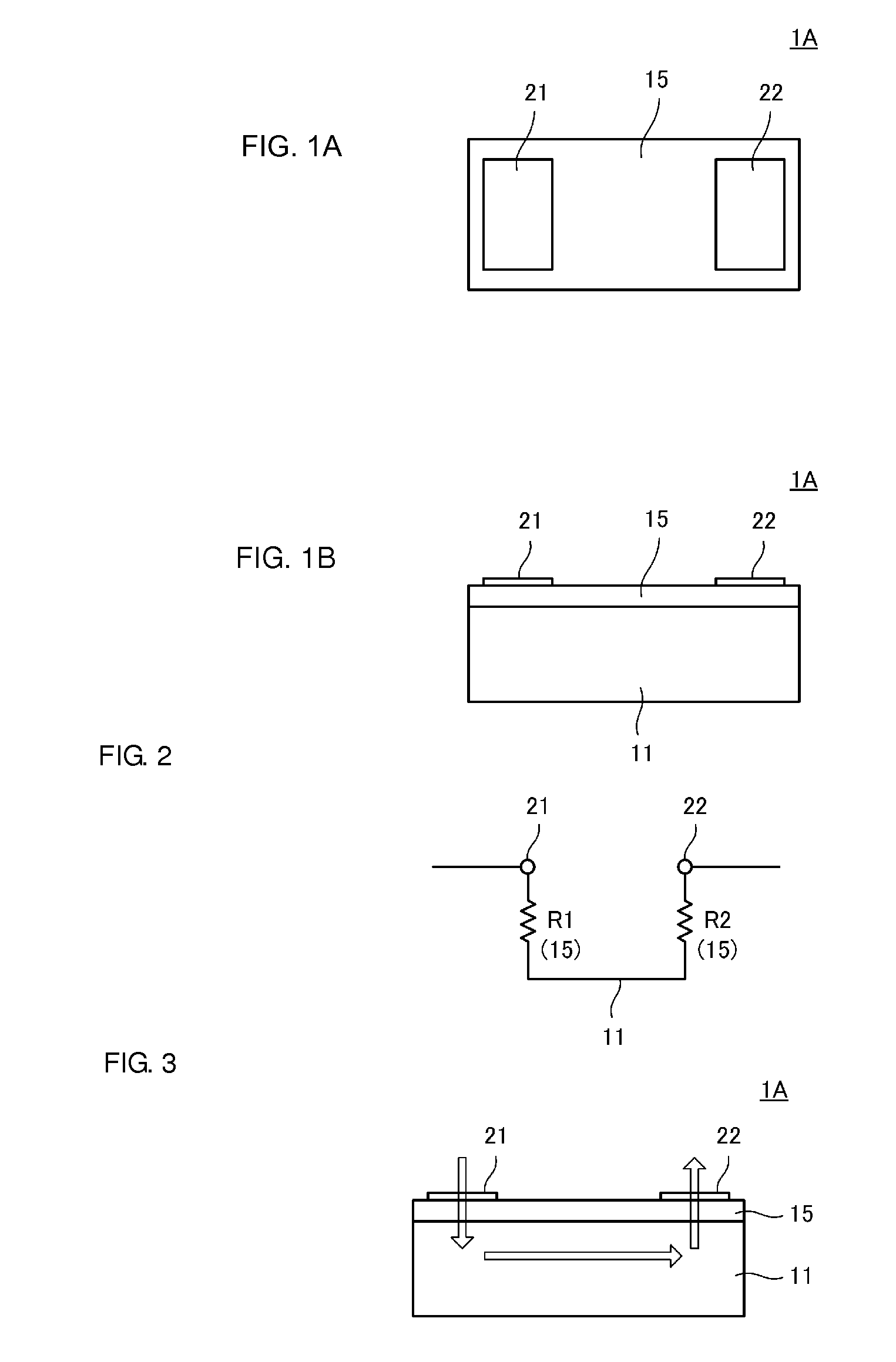
[0045]FIG. 1A is a plan view of a flexible thermistor, and FIG. 1B is a front view of the flexible thermistor. A flexible thermistor 1A includes a metal base 11, a thermistor layer 15 that is located on the metal base 11, and a pair of split electrodes 21 and 22 that are located on the thermistor layer 15. The metal base 11 is obtained preferably by firing a metal powder paste made into a sheet-shaped form. The thermistor layer 15 is obtained by preferably firing a ceramic slurry made into a sheet-shaped form. The split electrodes 21 and 22 are obtained preferably by firing an electrode material paste. The metal powder paste in a sheet-shaped form, the ceramic slurry in a sheet-shaped form, and the electrode paste are fired integrally with one another. It suffices that at least the metal base 11 and the thermisto...

second preferred embodiment

[0063]FIG. 6 is a cross-sectional view of a temperature sensor 6B according to a second preferred embodiment of the present invention. The temperature sensor 6B has a structure in which the flexible thermistor 1A is mounted on a flexible board 5B. The flexible board 5B includes the base layer 51, the wiring conductor layer 52 that is located on the base layer 51, and the cover layer 53 that is stacked over the base layer 51 and covers the wiring conductor layer 52.

[0064]In the example illustrated in FIG. 6, unlike the flexible board 5A illustrated in FIG. 5A with reference to the first preferred embodiment, the mounting surface of the flexible thermistor 1A is flat. That is, the thickness of the base layer 51 is made larger for the area where the wiring conductor layer 52 is not located. At the position of the cross section illustrated in FIG. 6, the surface of the base layer 51 on which the flexible thermistor 1A is mounted includes a projection 51P. The projection 51P preferably h...

third preferred embodiment

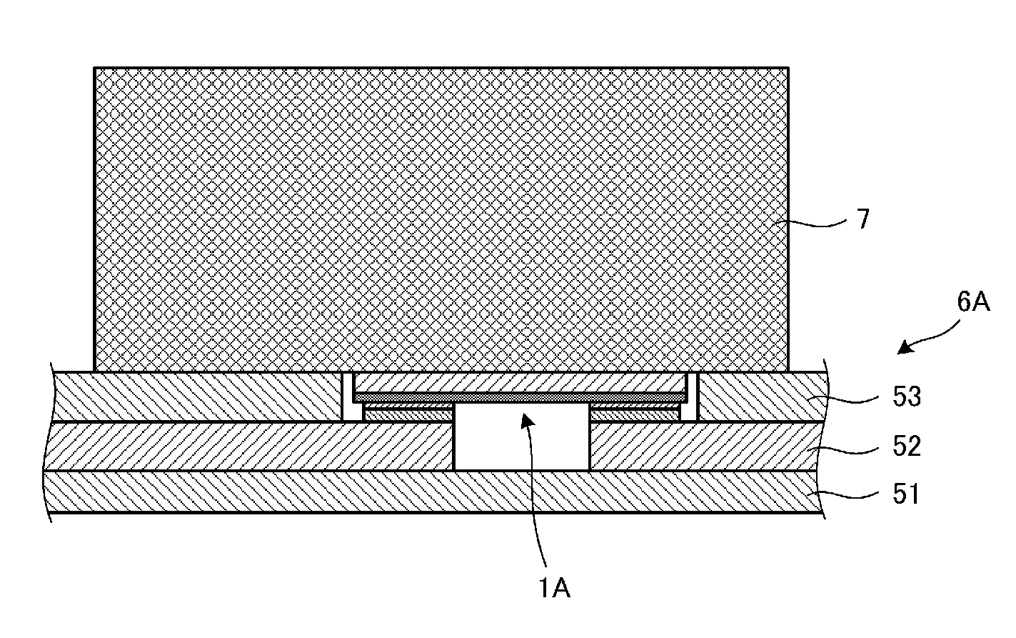
[0066]FIG. 7 is a cross-sectional view illustrating a temperature sensor attaching structure according to a third preferred embodiment of the present invention. In FIG. 7, the temperature sensor 6A preferably has the same structure as that described above with reference to the first preferred embodiment. The temperature detection object 7 is, for example, a heat generating element. The temperature sensor 6A is affixed to the temperature detection object 7. The flexible thermistor 1A comes into contact with or close proximity to the temperature detection object 7 in this state. That is, of surfaces of the temperature sensor 6A, the surface through which the flexible thermistor 1A is exposed is affixed to the temperature detection object 7.

[0067]As illustrated in FIG. 5, the height of the flexible thermistor 1A substantially coincides with the height of the surface of the cover layer 53, and moreover, the flexible thermistor 1A itself has flexibility. Therefore, the stress load applie...


PUM

PropertyMeasurementUnit
thicknessaaaaaaaaaa
thicknessaaaaaaaaaa
thicknessaaaaaaaaaa

Abstract

A flexible board includes a base layer, a wiring conductor layer that is located on the base layer, and a cover layer that is stacked over the base layer and covers the wiring conductor layer. A portion of the wiring conductor layer defines connecting portions that connect each of split electrodes of a flexible thermistor. The cover layer includes an opening that exposes the connecting portions, and receives the flexible thermistor. The split electrodes of the flexible thermistor are mounted on the connecting portions of the wiring layer. The height of the exposed surface of the flexible thermistor from the opening is substantially equal to the height of the surface of the cover layer.

Description

BACKGROUND OF THE INVENTION[0001]1. Field of the Invention[0002]The present invention relates to a temperature sensor and a temperature sensor attaching structure.[0003]2. Description of the Related Art[0004]In the related art, as devices become thinner and smaller, there are an increasing number of cases where a thermistor element used as a temperature sensor is mounted on a flexible board. For example, Japanese Unexamined Patent Application Publication No. 2010-015914 discloses a configuration in which a thermistor element is arranged on a flexible board.[0005]FIG. 23 is a cross-sectional view of a sensor unit 30 that detects the temperature of a power generating element disclosed in Japanese Unexamined Patent Application Publication No. 2010-015914. The sensor unit 30 has a flexible board 31, and a thermistor element (temperature information detecting element) 32 and signal lines 33 and 35 which are formed on the surface of the flexible board 31. The flexible board 31 is covered ...

Claims


Application Information

Patent Timeline
Patent Type & Authority Patents(United States)
IPC IPC(8): H01M10/48G01K7/22G01K1/14G06K19/077H01M50/569
CPCG01K1/14G06K19/07749H01M10/486G01K7/22Y02E60/10H01M50/569
Inventor TSUBAKI, SHUJIHAGA, TAKEOMIYAGAWA, KAZUTO
Owner MURATA MFG CO LTD
Why Eureka
Try Eureka