Device and method for pipeline rehabilitation

a technology for pipelines and hoses, applied in the direction of shaft linings, tunnel linings, underground chambers, etc., can solve the problems of difficult alignment of the hose-shaped part of the lining the problem of transporting such devices through the main line to the junction region of the building service line, so as to reduce the time for curing or setting

Active Publication Date: 2009-12-15
TRELLEBORG PIPE SEALS DUISBURG
View PDF33 Cites 22 Cited by
  • Summary
  • Abstract
  • Description
  • Claims
  • Application Information

AI Technical Summary

Benefits of technology

[0022]The lateral connecting hose is re-reversed, that is, turned over into the packer hose, before the rehabilitation in the packer hose together with the liner (lining), which essentially has the same shape as the mold. The air in the packer hose and connecting hose is suctioned. Therefore, a low pressure is formed and both the packer hose and the liner, which surrounds the packer hose, form a tight connection with the device. In this way, the liner on the device is secured against slipping.
[0028]All of the previously known devices use electromotors, typically servomotors, for moving within the main line. Such electromotors require power-supply lines for electrical energy. In addition, electric motors can be the source of sparks. Methane-bearing, and thus combustible, gases are frequently produced in wastewater pipes. Sparks increase the risk of fire or an explosion within the wastewater channels or wastewater pipes to be rehabilitated. For this reason, the invention proposes to use a pneumatic motor as the drive motor. Pneumatic motors are known in a wide variety of constructions. For example, as piston motors, they can have pistons that move in the axial direction, similar to an internal combustion engine, and that can generate drive torque by means of a crankshaft. The pistons run in cylinders, to which compressed air is supplied at certain times by means of valves. Also, pneumatic motors with several pistons arranged in an annular area are known, wherein the connecting rods of the pistons act on a swash plate. Here the air supply to the pistons is realized by means of piston ports. Finally, pneumatic motors with rotary pistons or turbine-like rotor disks are known. The device already provides a pressurized line for inflating the inflatable sleeve. This pressurized line can be used simultaneously as a supply for the operating medium of the pneumatic motor.
[0029]Furthermore, a practical embodiment of the invention can have a heating device for heating the curable pipe lining. Heating reduces the time for curing or setting the curable resin. The heating device can be formed, for example, by an electric heating coil.
[0032]As explained above, in one practical embodiment a ring can be used as the alignment body. The positioning means can be an inflatable sleeve, which presses a pipe lining made from a support material provided with curable resin against a pipe section to be rehabilitated. A cylindrical section of the pipe lining is pressed by a connecting hose of the inflatable sleeve into the junction of the building service line. During the transport of the pipe lining through the main line and before insertion of the annular alignment body, the connecting hose of the sleeve can be inverted into the interior of the sleeve together with the cylindrical section of the pipe lining by the annular alignment body. During transport of the sleeve through the main line to the pipe junction, the air can be suctioned from the sleeve. In this way, the sleeve lies tight against the device and is secured against slipping.

Problems solved by technology

The transporting of such devices through the main line to the junction region of the building service line has proven to be problematic in known devices.
In particular, the alignment of the hose-shaped part of the lining to the junction of the building service line is difficult.

Method used


Image

  • Device and method for pipeline rehabilitation
  • Device and method for pipeline rehabilitation
  • Device and method for pipeline rehabilitation

Examples


Embodiment Construction

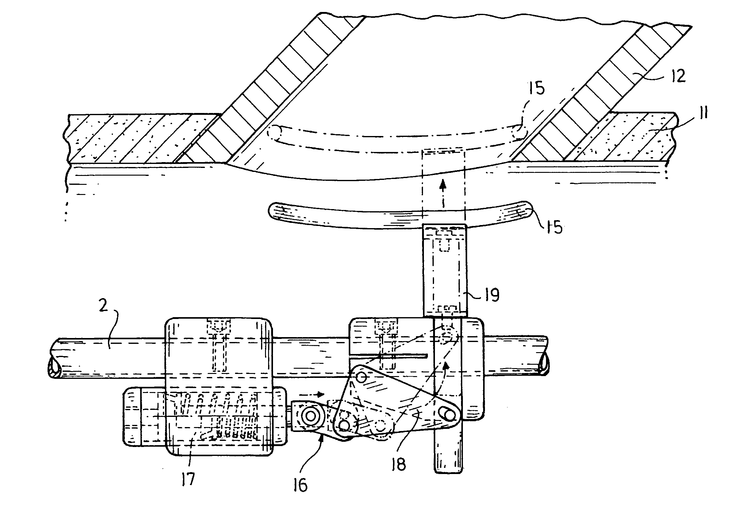
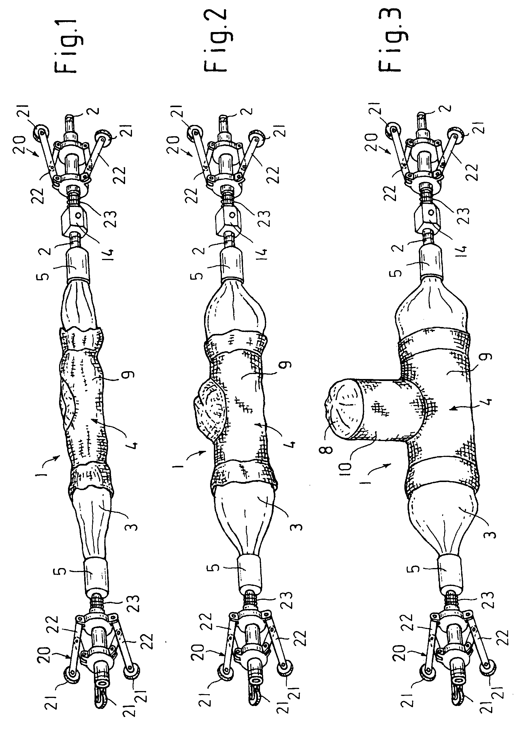
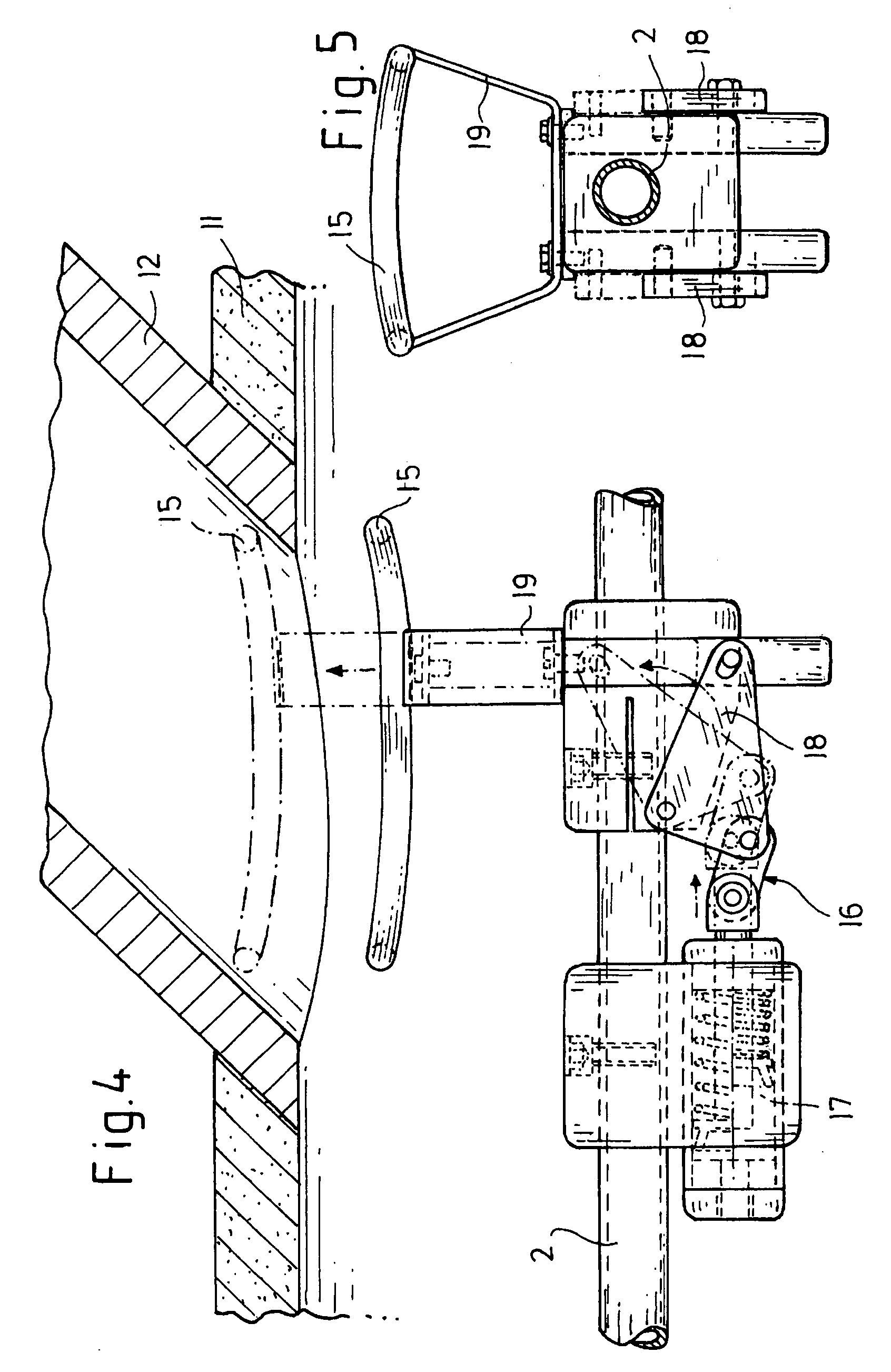
[0047]Referring now to the drawings, wherein like reference numerals refer to like parts throughout, there is seen in FIGS. 1-3 a packer 1 essentially consisting of a rigid packer rod 2, onto which the packer hose 3 and a flexible pipe lining 4 are pushed. Each of the two ends of the packer hose 3 is tensioned with a tensioning collar 5 around a cylindrical connection head 6 (cf. FIG. 7), so that an airtight connection is produced. The connection heads 6 are connected on their side rigidly and airtight to the packer rod 2. The connection head 6 shown on the left in FIG. 7 also receives a pressure line 7.

[0048]Furthermore, a connecting hose 8 is attached to the packer hose 3. This connecting hose has an angle to the packer hose 3 that corresponds to the angle between a building service line and a main line, which is to be rehabilitated in the junction region. In the FIGS. 1-3 this angle equals 90°. For rehabilitating the pipe connection shown in FIG. 7 the angle must equal 45°.

[0049]...


PUM


Abstract

A device and method for rehabilitating pipe connections is disclosed that simplifies the reliable transportation and positioning of a pipe lining relative to a junction region of a building service line to be lined. The device and method provides for rehabilitating the junction of a building connection from a main pipeline into the building service line. With a positioning mechanism, a curable pipe lining may be positioned at the junction of the building service line from the main line and, with a transport mechanism, the positioning mechanism and the pipe lining may be transported to the junction. An alignment body may be arranged so that it may move the transport mechanism and which can be moved into the junction of the building service line. A drive may move the alignment body into the junction of the building service line.

Description

BACKGROUND OF THE INVENTION[0001]1. Field of the Invention[0002]The present invention pertains to a device and method for pipeline rehabilitation. More specifically, it pertains to a device and method for rehabilitating the junction of a main pipeline and a building service line.[0003]2. Description of Prior Art[0004]A device for rehabilitating pipe joints is known, for which the positioning means is formed by a shield, the outer contours of which are adapted to the inner contours of the main sewer line in the region of the junction opening, so that it can be pressed against the region of the main sewer line that surrounds the junction opening by means of an extension arm. The extension arm is part of a transport unit, which can move in the main sewer line. The shield is moved in the main sewer line by means of the transport unit and is pressed against the main sewer line by means of the extension arm when it reaches the junction region. There is an outlet opening in the shield thro...

Claims


Application Information

Patent Timeline
Patent Type & Authority Patents(United States)
IPC IPC(8): F16L55/18F16L55/179F16L55/26
CPCF16L55/179E03F3/06F16L55/265
Inventor MUHLIN, MICHAEL
Owner TRELLEBORG PIPE SEALS DUISBURG
Why Eureka
Try Eureka