
Method for permanent calibration based on actual measurement

a permanent calibration and measurement technology, applied in the field of instruments, can solve the problems of inability to manufacture and reject instruments, and achieve the effect of high precision and high degree of precision

Active Publication Date: 2009-12-15
ORTHOSOFT ULC
View PDF23 Cites 28 Cited by
  • Summary
  • Abstract
  • Description
  • Claims
  • Application Information

AI Technical Summary

Benefits of technology

This approach significantly reduces calibration time in the operating room, ensures high precision, and prevents instrument rejection due to imprecision, enabling efficient and accurate use of instruments in CAS systems.

Problems solved by technology

If the end result of the measurements is outside the specifications of the manufacturing drawings, the instrument is rejected.
To achieve high precision, the manufacturing process can be expensive.

Method used


Image

  • Method for permanent calibration based on actual measurement
  • Method for permanent calibration based on actual measurement
  • Method for permanent calibration based on actual measurement

Examples


Embodiment Construction

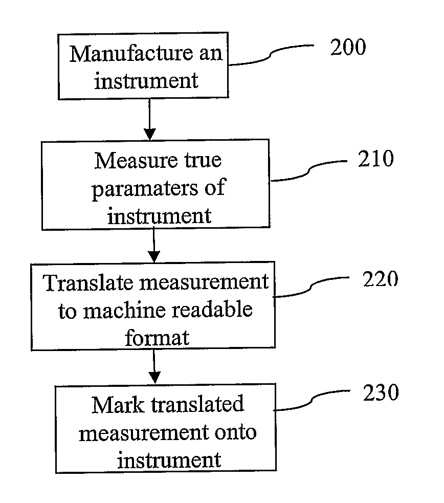
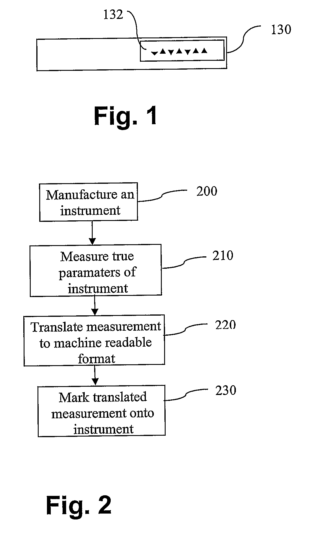
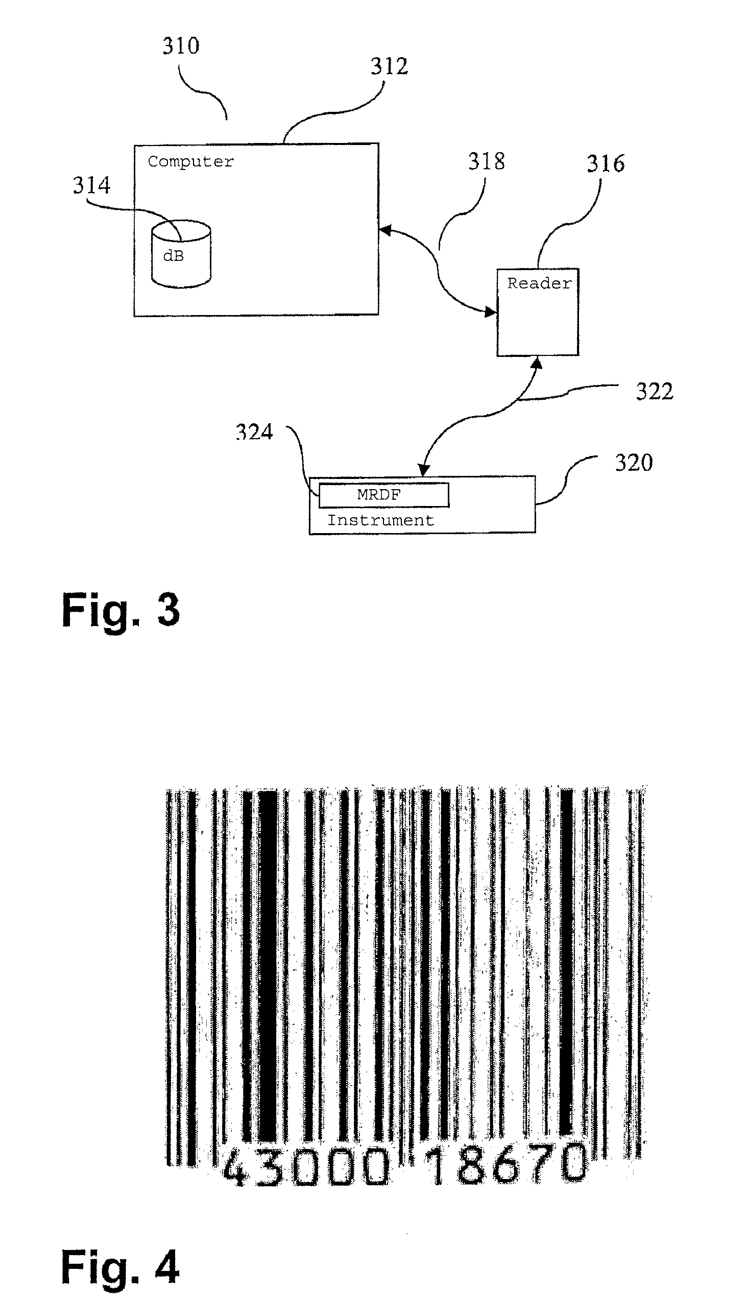
[0024]In a preferred embodiment of the present invention, at the end of the manufacturing process, the characteristics of the instrument needed by a CAS system are precisely measured. Those measurements, unique to that instrument, are recorded on a media and constitute the permanent calibration of that instrument. At the first use in an operating room, the instrument is selected and those measured characteristics, which are its true parameters, are fed to a CAS system, which can store the information. At further use, the operator can select the instrument per its identification and the system can use the stored information or read again the information related to the true parameters of the instrument.

[0025]Referring to the drawings and, more particularly, to FIG. 1, an instrument 130 with exemplary marking 132 is shown. The instrument 130 is manufactured according to manufacturing drawings containing measurement specifications and precision requirements. Once the instrument 130 is m...


PUM


Abstract

There is described a method of manufacturing a device to be used with a computer-aided surgery system, a method of calibrating the device, and the device itself. After fabrication, the device is measured to obtain true parameters thereof. The true parameters are stored on a storage medium associated with the device and include measurement data of high precision relating to dimensions of the device as well as to relative positioning of a tracker on the device with respect to the device. The true parameters are entered into the system and when the tracker is located in the 3D environment, the device can then be located in the 3D environment with a high degree of precision using the true parameters.

Description

CROSS-REFERENCE TO RELATED APPLICATION[0001]The present patent application claims priority on U.S. Provisional Patent Application No. 60 / 564,963, filed on Apr. 26, 2004, now expired.FIELD OF THE INVENTION[0002]The present invention generally relates to instrumentation and, more particularly, to a method for calibrating instrumentation used in a computer-assisted surgery environment.BACKGROUND OF THE INVENTION[0003]Instruments and implants such as surgical instruments and orthopedic implants are manufactured according to specifications usually illustrated in manufacturing drawings. The manufacturing drawings specify dimensions and precision requirements for the manufactured instruments. These precision requirements are stricter when the instruments or implants are used in an environment such as is encountered in a Computer Assisted Surgery (CAS) system.[0004]After the manufacturing of an instrument, comparative measurements of the manufactured instrument are made with the initial spe...

Claims


Application Information

Patent Timeline
Patent Type & Authority Patents(United States)
IPC IPC(8): G06F19/00A61B17/00A61B19/00G12B13/00
CPCA61B19/52A61B19/5244A61B2017/00526A61B2017/00725A61B2019/442A61B2019/566A61B2019/448A61B2019/5255A61B2019/5265A61B2019/5483A61B2019/446A61B2090/3983A61B90/96A61B90/36A61B2034/2055A61B2034/256A61B34/20A61B90/94A61B90/98A61B2034/2065
Inventor CHOUINARD, BENO TBRILLON, LOUISPELLETIER, BENO TJUTRAS, SEBASTIEN
Owner ORTHOSOFT ULC
Learn More