Rotation angle sensor and method for determining the absolute angular position of a body undergoes several rotations

a technology of rotation angle and absolute angular position, which is applied in the direction of instruments, measuring devices, using electrical means, etc., can solve the problems of different rotational speeds, angle determination errors within the scope of plausibility checks, and reduce the effective usable measuring range. , to achieve the effect of low rotational speeds

Active Publication Date: 2009-12-29
LEOPOLD KOSTAL GMBH & CO KG
View PDF24 Cites 23 Cited by
  • Summary
  • Abstract
  • Description
  • Claims
  • Application Information

AI Technical Summary

Benefits of technology

[0011]An advantage of such a magnetic steering angle sensor is that its simplified design results in low noise generation and the ability to use an evaluation method that is relatively simple and relatively less susceptible to interference.
[0016]The differently geared drive of the magnets, which are supported by respective code wheels, is designed such that more than one beat angle period is contained within the angular measuring range. That is, the beat angle periods are periodically repeated several times within the angular measuring range. As a result of dividing the angular measuring range into several beat angle periods, the slope of the beat angle within each period, corresponding to the number of beat angle periods within the angular measuring range, is greater than for a single beat angle extending over the angular measuring range. As a direct result of the greater slope, the distance is correspondingly greater between levels which are formed by the scaled beat angle and are used for determining the revolutions. Dividing the angular measuring range into two successive beat angle periods results in a twofold increase in the slope of the beat angle in each period. The greater slope of the beat angle results in a decrease in the edge region of the angular measuring range, which cannot be evaluated due to interference signal effects, such that the entire angular measuring range is effectively preserved.
[0017]To be able to distinguish the revolutions of the magnets despite the at least partial repetition of the beat angle period within the angular measuring range, the rotational angle positions of the magnets in the beat angle periods are differentiated from one another. As a result, the distance between the directly adjacent levels used for determining revolutions is greater than the possible error tolerance of a vehicle wheel angle position used within a plausibility check for examining the absolute angular measurement determined by the sensor. Errors in the angle determinations due to a faulty plausibility check are thus avoided. For an angular measuring range having two beat angle periods, the offset is 180°, for example, assuming that the measuring range of a sensor element is 360°. This angular shift represents additional information from which the beat angle period may be determined.
[0019]The difference in gear ratios of the code wheels of the sensor is greater than the difference in gear ratios of the code wheels of a typical magnetic steering angle sensor. This affords the opportunity of associating two different sizes of drive wheels having a correspondingly different number of teeth with the shaft. The diameter of the shaft is typically much larger than the diameter of either code wheel so that drive wheels having a different number of teeth may be easily provided. In one embodiment, the code wheels each have the same number of teeth, and the shaft supports two drive wheels, each having a different number of teeth. The difference in the number of teeth of the two drive wheels is between five and seven teeth. When two drive wheels having a different number of teeth are used, the code wheels themselves likewise may have different numbers of teeth.

Problems solved by technology

A problem with the magnetic steering angle sensor is that magnetic interference results in a reduction of the effectively usable measuring range.
This results in error in the angle determinations within the scope of the plausibility check of the determined absolute angular position.
This results in very different drive ratios for the magnets and thus results in very different rotational speeds.

Method used


Image

  • Rotation angle sensor and method for determining the absolute angular position of a body undergoes several rotations
  • Rotation angle sensor and method for determining the absolute angular position of a body undergoes several rotations
  • Rotation angle sensor and method for determining the absolute angular position of a body undergoes several rotations

Examples


Embodiment Construction

)

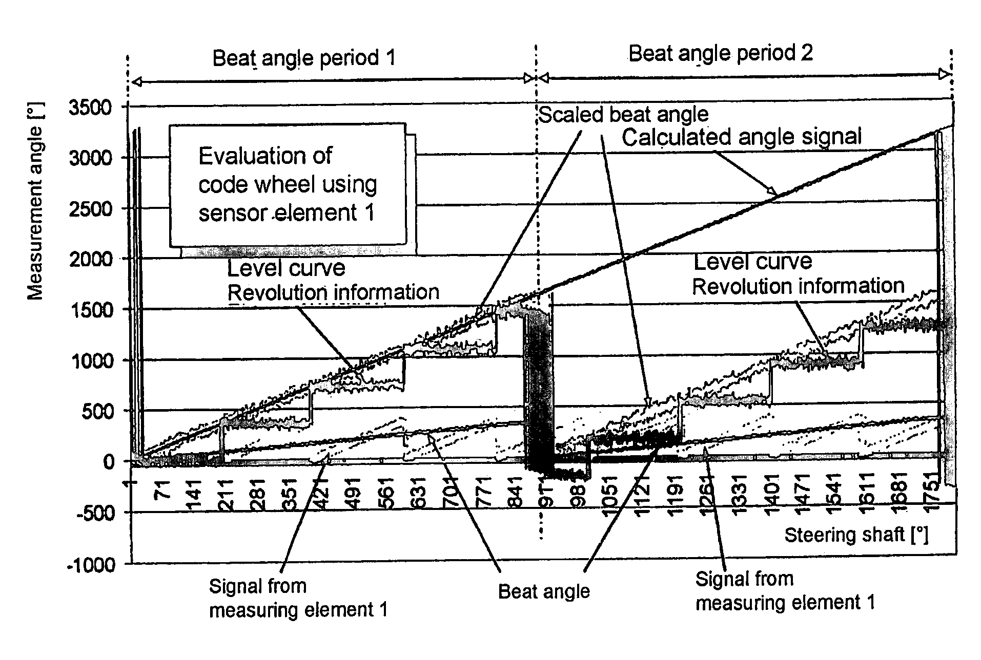
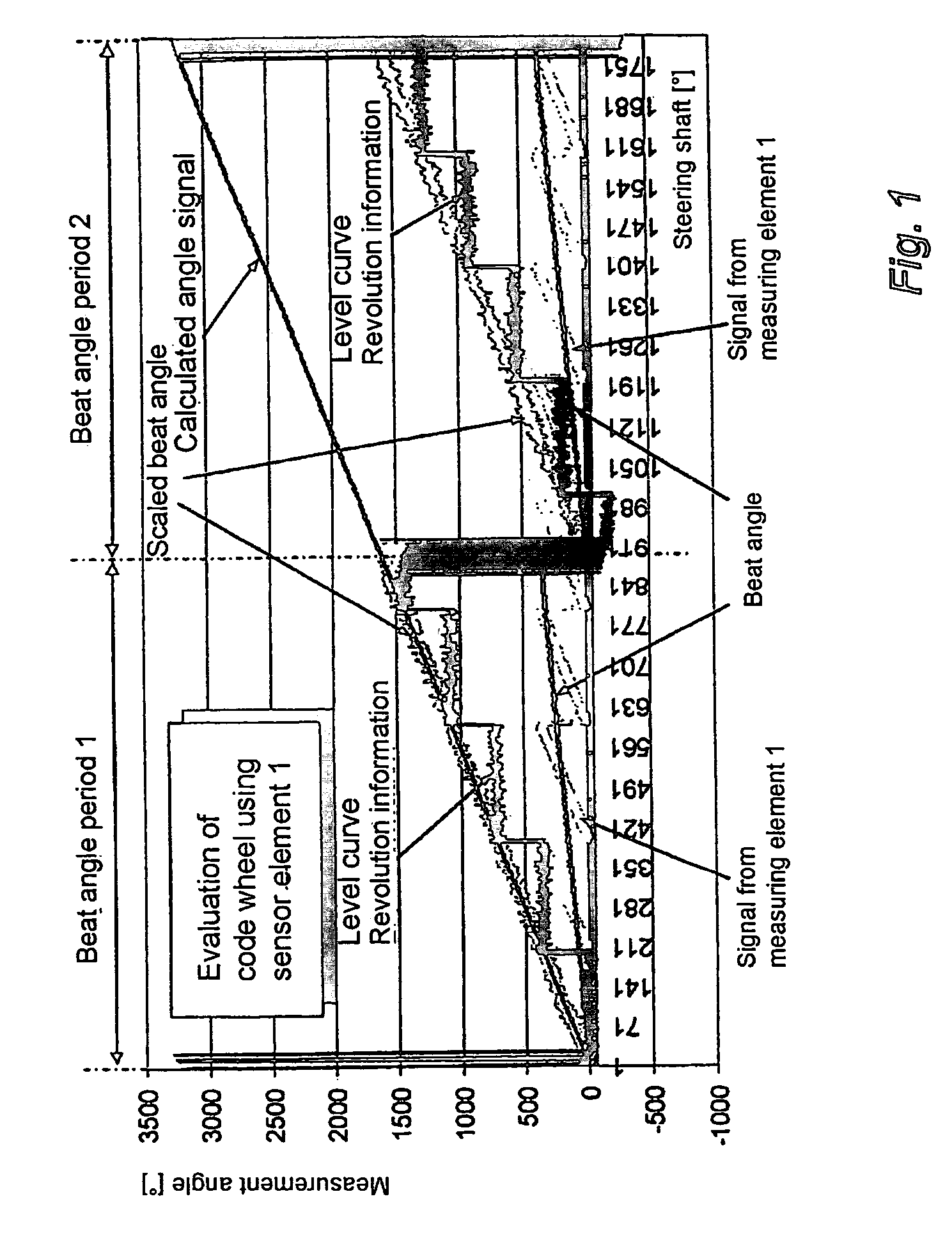
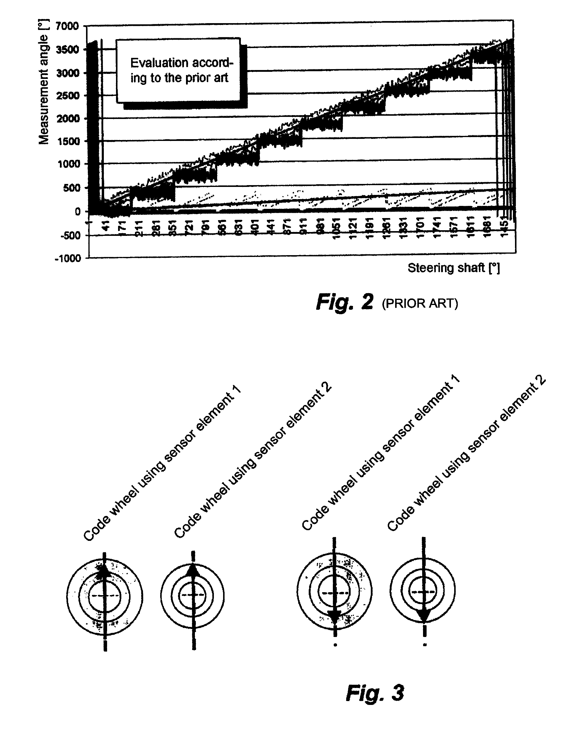
[0026]Turning initially to FIGS. 4a and 4b, a magnetic steering angle sensor 10 in accordance with an embodiment of the present invention determines the absolute angular position of a rotatable body 12 (such as the steering shaft of a vehicle) which can rotate through several revolutions (e.g., 1800°). The sensor 10 determines the absolute angular position of the shaft 12 over an angular measuring range corresponding to the range of available rotation of the shaft. In this embodiment, as described in U.S. Pat. No. 5,930,905, which is hereby incorporated by reference, a drive wheel 11 engages the shaft 12 to rotate therewith and the sensor 10 includes first and second magnetically operated measuring elements. Each measuring element includes a respective code wheel 14, 16 having a respective magnet 18, 20 (i.e., a magnetic pickup element). The code wheels 14, 16 engage the drive wheel 11 (via a toothed gear ring of the drive wheel 11 and respective toothed gear rings of the code whee...


PUM


Abstract

A sensor determines the absolute angular position of a body that can rotate through rotations. The sensor includes two code wheels which rotate as the body rotates. The code wheels are driven at a different gear ratio such that the code wheels rotate faster than the body and the code wheels rotate at different rates. Two sensor elements respectively determine the rotational angle positions of the code wheels. The difference between the rotational angle positions is a beat angle. The different gear ratio is selected such that beat angle periods are in an angular measuring range of the sensor and the absolute angular positions of the code wheels in the beat angle periods is different. The absolute angular positions of the code wheels in successive beat angle periods is offset by the nth part of the measuring range of a sensor element, where n is number of beat angle periods.

Description

CROSS-REFERENCE TO RELATED APPLICATIONS[0001]This is a continuation-in-part of International Application PCT / EP2007 / 001126, published in German, with an international filing date of Feb. 9, 2007, which claims priority to DE 10 2006 006 359.7, filed Feb. 11, 2006, the disclosures of which are both hereby incorporated by reference.BACKGROUND OF THE INVENTION[0002]1. Field of the Invention[0003]The present invention relates to a rotational angle sensor for determining the absolute angular position of a body such as a vehicle steering shaft that can rotate through several rotations (i.e., rotatable by more than 360°) in which the sensor includes first and second measuring elements each having a magnet which rotates relative to a respective magnetic sensor element as the body rotates with the magnets being driven at different gear ratios such that the difference between the rotational angle positions of the magnets results in a “beat angle” in which more than one beat angle period is con...

Claims


Application Information

Patent Timeline
Patent Type & Authority Patents(United States)
IPC IPC(8): G01B7/30
CPCG01D5/145
Inventor MAIER, OLIVERSCHIRP, CHRISTIAN
Owner LEOPOLD KOSTAL GMBH & CO KG
Why Eureka
Try Eureka