Multiband camera system

a multi-band camera and camera body technology, applied in the field of multi-band camera systems, can solve the problems of limited detection band of such cameras, difficult production of multi-band cameras, and high processing costs and inefficiency

Inactive Publication Date: 2010-01-12
HONEYWELL INT INC
View PDF13 Cites 47 Cited by
  • Summary
  • Abstract
  • Description
  • Claims
  • Application Information

AI Technical Summary

Problems solved by technology

However multiple band cameras are difficult to produce.
However, such processing is expensive and inefficient.
Moreover, the detection band in such cameras is limited by the nature of the sensor material.
Although this arrangement produces images in multiple frequency bands, operating conditions such as vibrations, thermal conditions etc. may cause relative movement between the multiple image sensors.
This relative movement results in misalignment when the images are overlaid.

Method used


Image

  • Multiband camera system
  • Multiband camera system
  • Multiband camera system

Examples


Embodiment Construction

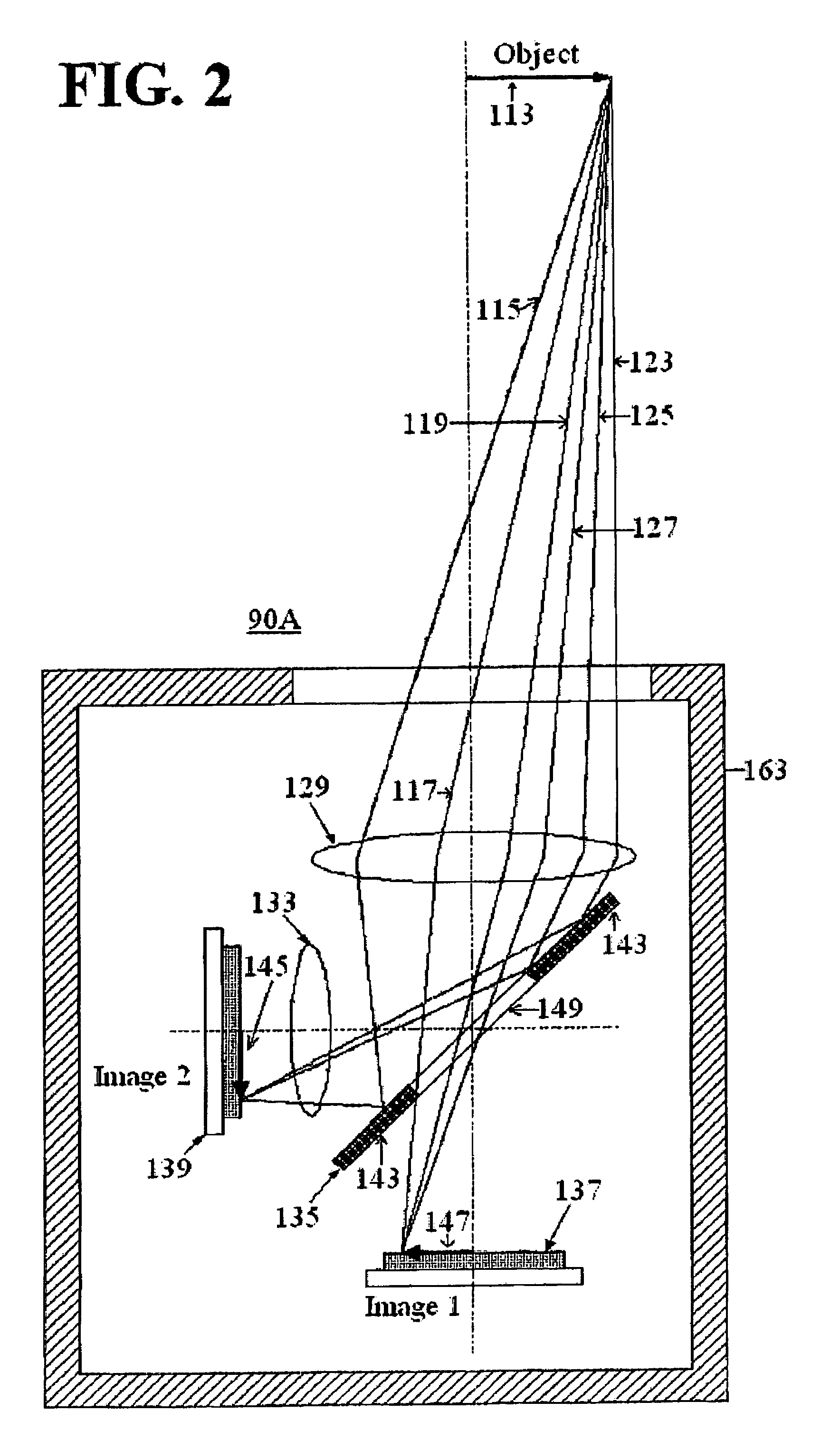
[0021]Aspects of the invention are more specifically set forth in the accompanying description with reference to the appended figures. FIG. 2 illustrates a configuration for a multiband camera system 90A to which principles of the present invention may be applied to enable image alignment. As shown in FIG. 2, the multiband camera system 90A according to this embodiment includes: an optical front end system 129; an optional corrective optics system 133; an image splitter device 135; a first sensor 137; a second sensor 139; and a multiband camera system frame 163.

[0022]The first sensor 137 and second sensor 139 are separate image sensors, each optimized for use in a target band. Two sensors are shown in FIG. 2, but more than two sensors may be present. Target bands for the first sensor 137 and the second sensor 139 are frequency bands from the electromagnetic spectrum. Two optical paths exist in multiband camera system 90A, corresponding to the first sensor 137 and to the second senso...


PUM


Abstract

A multiband camera system includes: a first sensor for generating a first object image and a first alignment image in a first frequency band; a second sensor for generating a second object image and a second alignment image in a second frequency band; and an internal alignment assembly. A splitter directs radiation in the first frequency band from the object to the first sensor to form the first object image, directs radiation in the second frequency band from the object to the second sensor to form the second object image, directs radiation in the first frequency band from the internal alignment assembly to the first sensor to form the first alignment image, and directs radiation in the second frequency band from the internal alignment assembly to the second sensor to form the second alignment image. The first alignment image and the second alignment image establish a reference for aligning the first and second object images.

Description

BACKGROUND OF THE INVENTION[0001]1. Field of the Invention[0002]The present invention relates to camera systems, and more particularly to a multiband camera system having multiple image sensors and an internal alignment assembly.[0003]2. Description of the Related Art[0004]For many military and civilian applications, such as industrial machine vision, laser-beam profiling, military imaging, etc., there is a need for simultaneous capture of high resolution images in multiple frequency bands, such as, for example, shortwave infrared and visible frequencies, thermal and visible frequencies, etc. However multiple band cameras are difficult to produce.[0005]One dual band unit camera is capable of imaging visible and shortwave infrared (SWIR) wavelengths. The key element in this dual band unit camera is a backside-illuminated 320×240-pixel InGaAs photodiode array, with a thinned InP substrate. Visible light is typically absorbed by the InP substrate because of its 920 nm cutoff. However, ...

Claims


Application Information

Patent Timeline
Patent Type & Authority Patents(United States)
IPC IPC(8): H04N5/225
CPCG02B27/1013G02B27/143G02B27/32H04N5/33H04N5/332H04N9/093G02B13/146H04N23/11H04N23/15
Inventor CERNASOV, ANDREI
Owner HONEYWELL INT INC
Why Eureka
Try Eureka