X-ray CT system

a computed tomography and x-ray technology, applied in the field of scattering radiation correction, can solve the problems of reducing the effective area of an x-ray detection surface, degrading the use efficiency of x-rays, and unable to ignore the negative effect of scattered radiation oriented in the direction of the array of detectors, etc., and achieve the effect of performing scattering radiation correction more precisely

Inactive Publication Date: 2007-03-13
GE MEDICAL SYST GLOBAL TECH CO LLC
View PDF25 Cites 49 Cited by
  • Summary
  • Abstract
  • Description
  • Claims
  • Application Information

AI Technical Summary

Benefits of technology

[0009]Therefore, an object of the present invention is to provide an X-ray CT system capable of correcting scattered radiation more highly precisely.
[0011]According to the present invention, there is provided an X-ray CT system capable of performing scattered radiation correction more highly precisely.

Problems solved by technology

On the other hand, when the number of arrays of detectors increases, the adverse effect of scattered radiation oriented in the direction of the arrays of detectors cannot be ignored.
However, this method brings about a decrease in an effective area of an X-ray detection surface.
Moreover, an issue of an angle at which an X-ray tube is looked up cannot be ignored, and the use efficiency of X-rays is degraded.
Moreover, an increase in the cost of hardware cannot be avoided because the collimator must be disposed highly precisely.
However, correction of scattered radiation to be performed in the X-ray computed tomography system disclosed in Patent Document 1 is not devised in consideration of the situation that an amount of scattered radiation entering each detector array is not even.

Method used


Image

  • X-ray CT system
  • X-ray CT system
  • X-ray CT system

Examples


Embodiment Construction

[0019]Referring to drawings, an embodiment will be described below.

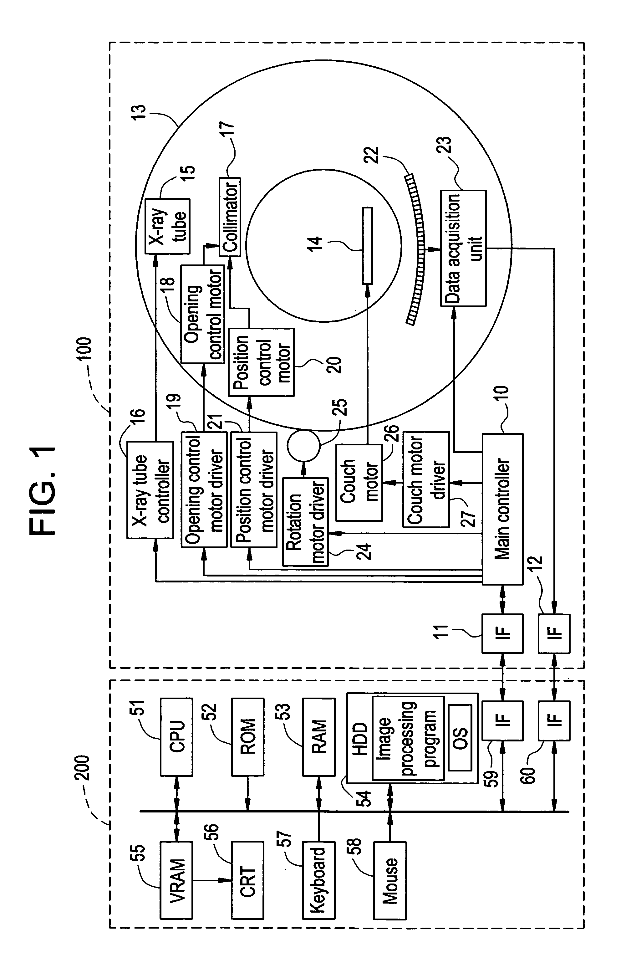
[0020]FIG. 1 shows the configuration of an X-ray CT system in accordance with an embodiment.

[0021]As illustrated, the present system comprises: a gantry 100 that irradiates X-rays to a subject (patient) and detects X-rays transmitted by the subject; and an operator console 200 that is used to designate various actions to be performed in the gantry 100 and that reconstructs and displays a tomographic image on the basis of data sent from the gantry 100.

[0022]The gantry 100 has a main controller 10 that is responsible for control of the entire gantry and other components described below.

[0023]Reference numerals 11 and 12 denote interfaces via which the gantry 100 communicates with the operator console 200. Reference numeral 13 denotes a rotary assembly that has a bore through which a subject lying down on a patient couch 14 is transported in a direction perpendicular to the drawing (in general, a direction corresponding...


PUM

PropertyMeasurementUnit
projection angleaaaaaaaaaa
widthaaaaaaaaaa
CTaaaaaaaaaa

Abstract

A method for performing scattered radiation correction. The position of a collimator and the width of a slit are adjusted so that direct radiation will fall on one of a plurality of arrays of detectors. A predetermined phantom is scanned. The scan is performed relative to each of the plurality of arrays of detectors. Based on data detected during each scan, scattered radiation correction data is produced. The produced scattered radiation correction data is used to correct projection data acquired by scanning a subject.

Description

CROSS REFERENCE TO RELATED APPLICATIONS[0001]This application claims the benefit of Japanese Application No. 2003-203226 filed Jul. 29, 2003.BACKGROUND OF THE INVENTION[0002]The present invention relates to a scattered radiation correcting technology to be implemented in an X-ray computed tomography (CT) system that produces an X-ray tomographic image of a subject through X-irradiation.[0003]The major object of X-ray CT systems is to acquire projection data provided by X-rays having passed through a subject, and to reconstruct an X-ray tomographic image from the projection data. More particularly, first, a subject is asked to lie down on a patient couch, and transported to a bore of a gantry. A rotary assembly of the gantry in which an X-ray detecting mechanism including an X-ray tube and X-ray detectors is incorporated as an integral part thereof is driven to rotate. X-rays are irradiated to the subject from different angles, and X-rays irradiated at the respective angles and trans...

Claims


Application Information

Patent Timeline
Patent Type & Authority Patents(United States)
IPC IPC(8): G01N23/083A61B6/00A61B6/03A61B6/06G03B42/02
CPCA61B6/032A61B6/583A61B6/4085A61B6/06A61B6/03
Inventor HAGIWARA, AKIRA
Owner GE MEDICAL SYST GLOBAL TECH CO LLC
Why Eureka
Try Eureka