
Lamp filament

a technology of filaments and lamps, applied in the field of lamp filaments, can solve the problems of tungsten coil sagging over time, coil sagging, and increased current passing through the coil with a concomitant increase in coil temperature, so as to increase the effective emissivity of secondary wires, enhance visible and ir radiated power, and increase the effective radiative surface area of the coil.

Inactive Publication Date: 2008-01-24
LEDVANCE LLC
View PDF9 Cites 4 Cited by
  • Summary
  • Abstract
  • Description
  • Claims
  • Application Information

AI Technical Summary

Benefits of technology

[0006] It is another object of the invention to enhance the operation of tungsten filaments.
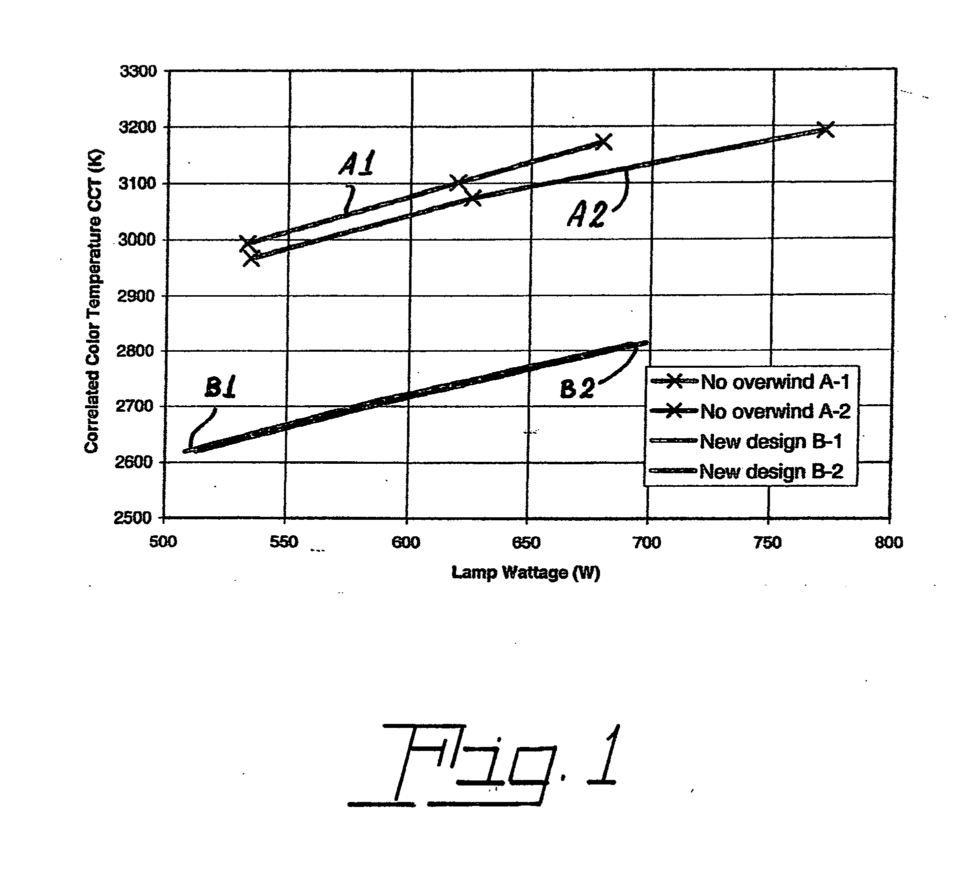
[0009] The overwind increase the effective radiative surface area of the coil and also produces a blackbody cavity effect that increases the effective emissivity of the secondary wire. These effects enhance the visible and IR radiated power per unit length and, therefore, lowers the filament temperature when operating at a fixed power. Operating at a lower temperature reduces the sag rate and thus increases lamp life. Alternatively, a lamp according to this aspect of the invention can be operated at higher powers to produce more IR radiation at the same color temperature

Problems solved by technology

The tungsten coil will sag over time, especially when the operating temperature exceeds 3000 C, as is known to happen in some demanding applications.
In the case of lamps used in a vertical, base-up position, that is, with the axis of the coil perpendicular to the ground, the sag will eventually cause a short circuit in the filament, which will lead to higher currents passing through the coil with a concomitant increase in coil temperature.
The increase in temperature accelerates the coil sagging and causes a further compression of the turns of the coil.

Method used


Image

  • Lamp filament
  • Lamp filament
  • Lamp filament

Examples


Embodiment Construction

[0014] For a better understanding of the present invention, together with other and further objects, advantages and capabilities thereof, reference is made to the following disclosure and appended claims taken in conjunction with the above-described drawings.

[0015] Referring now to the drawings with greater particularity, there is shown in FIG. 1 a graph illustrating a comparison between lamps of the prior art and lamps employing the overwind of the invention. From FIG. 1 it can clearly be seen that lamps employing the overwind (lamps B1 and B2) have a lower temperature when operated at the same power then the prior art lamps (A1 and A2). Since the coil sag rate is lower at the reduced temperatures, the life is extended.

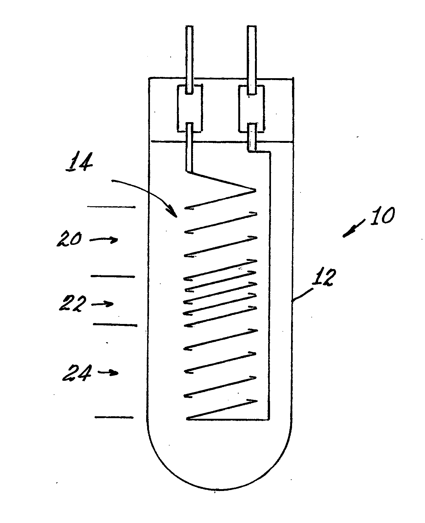
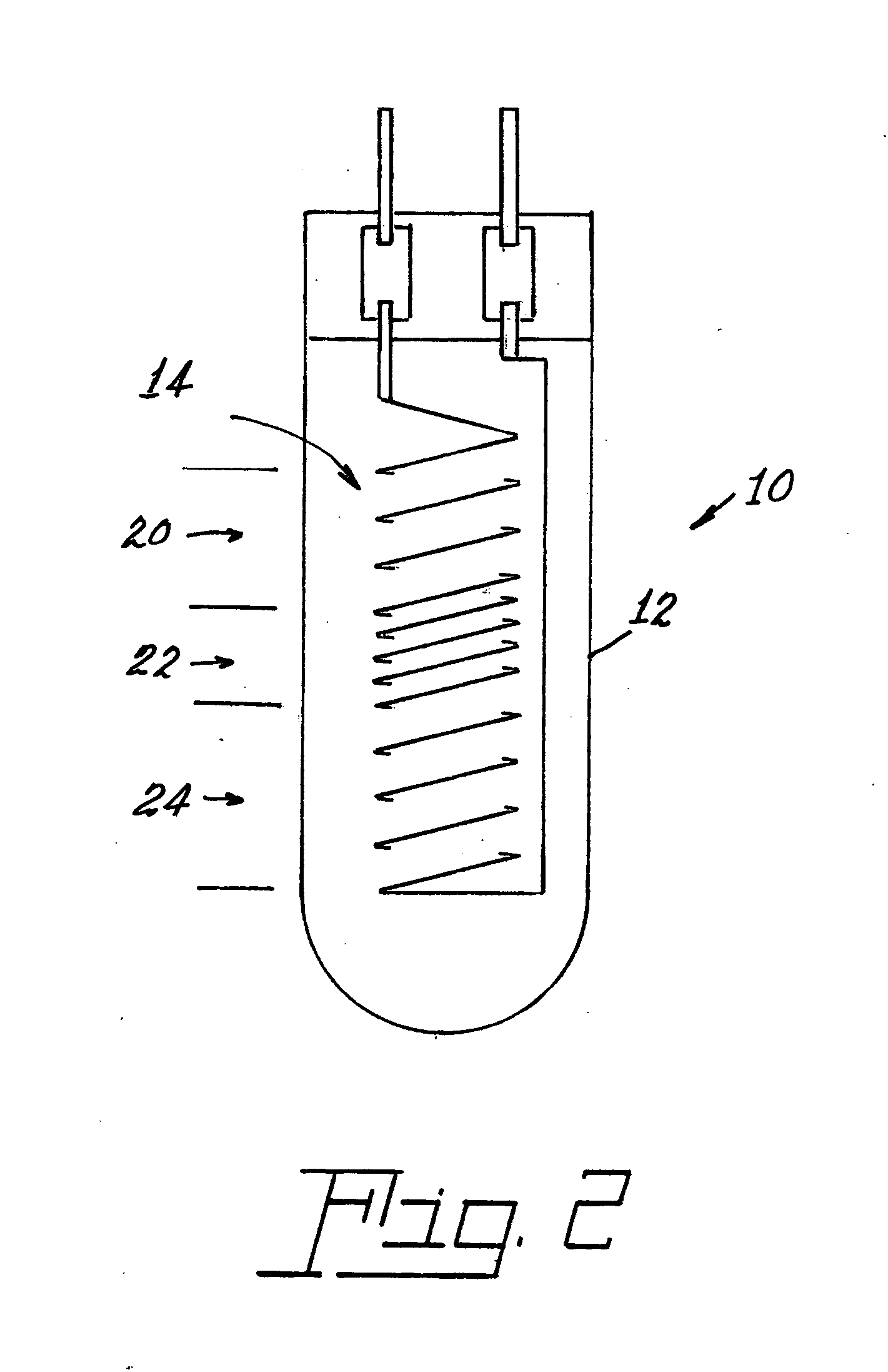
[0016] Additionally, the life of the filament can be further increased by varying the pitch between the coils, as is shown diagrammatically in FIG. 2. Therein, a lamp 10, designed for base-up operation, has an envelope 12 enclosing a coiled coil filament 14. The co...


PUM


Abstract

A base-up incandescent lamp (10) includes a coiled-coil filament (14) that has a primary wire (18) and a secondary wire (16), the primary wire (18) comprising an overwind that overlies the secondary wire (16) and provides a lower filament temperature and, therefore, less filament sag and a concomitant longer lamp life.

Description

TECHNICAL FIELD [0001] This invention relates to lamp filaments and particularly to such filaments having a lower temperature and longer life than conventional coil designs. It is particularly useful with infrared (IR) lamps. BACKGROUND ART [0002] In typical incandescent lamps a tungsten coil of a given length and wire diameter is used to radiate both visible light and IR radiation when an electrical current is passed through it. [0003] The tungsten coil will sag over time, especially when the operating temperature exceeds 3000 C, as is known to happen in some demanding applications. It is known that the addition of potassium will reduce, but not eliminate, the coil sagging, as is shown from U.S. Pat. No. 2,012,825. [0004] In the case of lamps used in a vertical, base-up position, that is, with the axis of the coil perpendicular to the ground, the sag will eventually cause a short circuit in the filament, which will lead to higher currents passing through the coil with a concomitant...

Claims


Application Information

Patent Timeline
IPC IPC(8): H01K1/14H01K9/00
CPCH01K1/14
Inventor LI, JASON J.KASAK, ALEXANDER N.SELL, HEINZ W.LENEF, ALAN L.FLEMING, RAYMOND T.LAIRD, RICHARD C.WINNINGHAM, MATTHEW
Owner LEDVANCE LLC
Learn More