
Radiation resistant inverted metamorphic multijunction solar cell

a solar cell, inverted technology, applied in the direction of basic electric elements, electrical apparatus, semiconductor devices, etc., can solve the problems of multi-junction solar cells, and achieve the effects of improving the performance of metamorphic multi-junction solar cells, and reducing the risk of radiation exposur

Inactive Publication Date: 2018-05-17
SOLAERO TECH CORP
View PDF3 Cites 0 Cited by
  • Summary
  • Abstract
  • Description
  • Claims
  • Application Information

AI Technical Summary

Benefits of technology

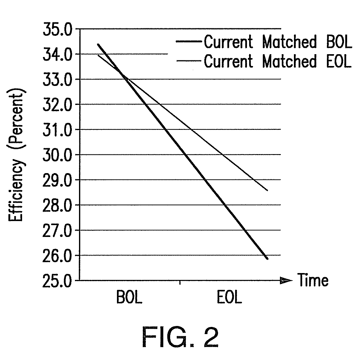
[0008]The present invention aims to improve the performance of a metamorphic multijunction solar cell having at least two InGaAs solar subcells in an AM0 environment. In accordance with the present invention, a mismatch is introduced into the short circuit currents associated with the solar subcells of the solar cell at beginning of life to allow for greater deterioration of the conversion efficiency of the at least two InGaAs solar subcells during deployment of the solar cell in an AM0 environment. Contrary to expectations given the increased InAs content, an InGaAs solar subcell having a lower band gap energy has been found to be more radiation resistant than an InGaAs solar subcell having a higher band gap energy. As a result, at the beginning of the life of the solar cell, the short circuit current associated with the lower band gap InGaAs solar subcell is made less than the short circuit current associated with the higher band gap energy InGaAs solar subcell. In embodiments of the invention, the short circuit current associated with the lower band gap InGaAs solar subcell is made less than the short circuit current associated with the higher band gap energy InGaAs solar subcell by an amount in the range of 2% to 6%.

Problems solved by technology

Thus, incorporating an InGaAs subcell into a “radiation hard” multijunction solar cell presents a challenge.

Method used


Image

  • Radiation resistant inverted metamorphic multijunction solar cell
  • Radiation resistant inverted metamorphic multijunction solar cell
  • Radiation resistant inverted metamorphic multijunction solar cell

Examples


Embodiment Construction

[0013]Details of the present invention will now be described, including exemplary aspects and embodiments thereof. Referring to the drawings and the following description, like reference numbers are used to identify like or functionally similar elements, and are intended to illustrate major features of exemplary embodiments in a highly simplified diagrammatic manner. Moreover, the drawings are not intended to depict every feature of actual embodiments nor the relative dimensions of the depicted elements, and are not drawn to scale.

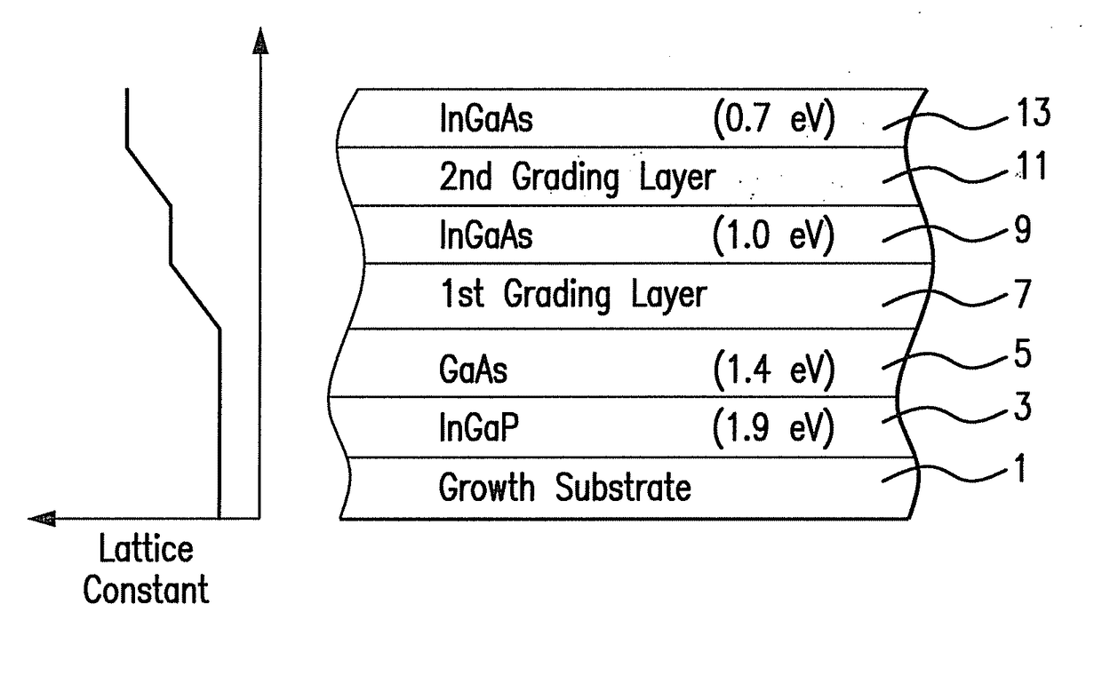
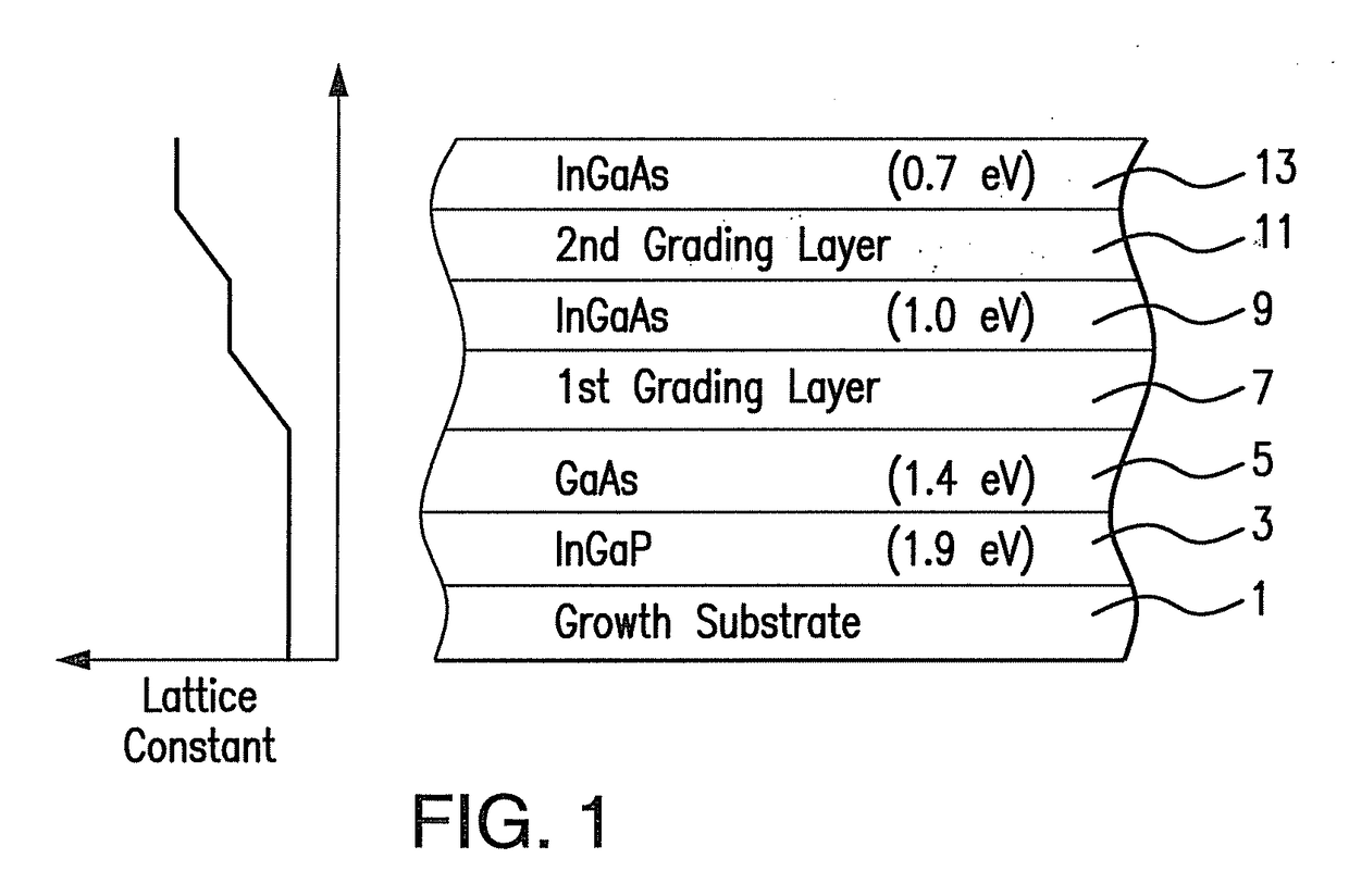
[0014]FIG. 1 schematically shows an inverted metamorphic four junction solar cell, hereafter referred to as an IMM4J solar cell. In particular, FIG. 1 shows an exploded view of the main layers of the IMM4J solar cell before removal of the growth substrate 1. It will be appreciated that the IMM4J solar cell shown in FIG. 1 is typically reverse-mounted onto a surrogate substrate and the growth substrate 1 is removed prior to use.

[0015]An InGaP solar subcell ...


PUM


Abstract

A multijunction solar cell including a first solar subcell having a first band gap and a first short-circuit current; a second solar subcell disposed over the first solar subcell and having a second band gap greater than the first band gap and a second short-circuit current greater than the first short-circuit current by an amount in the range of 2% to 6%; a third solar subcell disposed over the second solar subcell and having a third band gap greater than the second band gap and a third short-circuit current less than the first short-circuit current by an amount in the range of 2% to 6%; and a fourth solar subcell disposed over the third solar subcell having a fourth band gap greater than the third band gap, and a fourth short-circuit current less than the third short-circuit current by an amount in the range of 6% to 10%, so that at an “end of life” state of the multijunction solar cell in an AM0 space environment the short-circuit current of each of the subcells are substantially identical.

Description

CROSS-REFERENCE TO RELATED APPLICATIONS[0001]This application is a continuation of application Ser. No. 13 / 491,390, filed Jun. 7, 2012, which is incorporated herein by reference in its entirety.GOVERNMENT RIGHTS STATEMENT[0002]This invention was made with government support under Contract No. FA9453-09-C-0371 awarded by the U.S. Air Force. The Government has certain rights in the invention.BACKGROUND OF THE INVENTION1. Field of the Invention[0003]The present invention relates to a metamorphic multijunction solar cell for a space radiation environment, sometimes referred to as an air mass zero (AM0) environment. Such solar cells are used power sources by many satellites.2. The Background Art[0004]The desire for higher conversion efficiency has driven the development of multijunction solar cells, that is solar cells having two or more solar subcells with different band gaps and arranged in order of decreasing band gap so that high energy radiation is absorbed by the first solar subcel...

Claims


Application Information

Patent Timeline
Patent Type & Authority Applications(United States)
IPC IPC(8): H01L31/0687
CPCH01L31/06875Y02E10/544H01L31/041
Inventor PATEL, PRAVINCHO, BENJAMIN
Owner SOLAERO TECH CORP
Learn More