Combination flashlight and camera system

a combination flashlight and camera technology, applied in the field of detection and collection of evidence, can solve the problems of significant change, loss of opportunity to collect important evidence, and place the officer at risk of being hurt, so as to improve the process of evidence collection and improve the effect of convenience and eas

Inactive Publication Date: 2010-01-12
LYNK3 TECH
View PDF8 Cites 22 Cited by
  • Summary
  • Abstract
  • Description
  • Claims
  • Application Information

AI Technical Summary

Benefits of technology

[0019]A distinct advantage of the present invention, is that an enthusiast can not only observe the activity of a desired subject, but can also record that subject with the same convenience and ease as holding and operating a conventional flashlight with a single hand.
[0020]U.S. Pat. No. 6,692,432 issued to Yarush, et al is an example of a camera developed for a special function. Yarush, et. al. discloses an endoscope in which a lens is optically coupled to an imaging system and the light source transmits light through the lens. As noted in Yarush, “The practitioner then views the illuminated object on the video monitor.” In Yarush, a video capability is added to an endoscope and the camera utilizes the light source of the endoscope.
[0021]In the invention disclosed herein, various data collection sensors are integrated with a flashlight thereby improving the process of evidence collection.Unfulfilled NeedsNeed for Multi-Functional Devices
[0022]In the course of a safety and security officer's routine work, there are occasions when recording an image of a scene or object is desirable. On the other hand, there are times when an area must also be secured to prevent tampering with a scene until photographic or other evidence can be obtained. And, in certain circumstances, for example when an officer is in hot pursuit or in the presence of an extreme hazard, such as a fire, the officer might have to leave an area of interest. In such circumstances, unless the officer happens to be carrying a camera, the opportunity to collect important evidence is lost. However, due to the added weight of carrying a camera, the tendency is to leave the camera behind, in another location, such as an office or vehicle, and to fetch the camera only when it is later unexpectedly found to be needed.
[0023]Missed opportunities to collect evidence are not limited to the collection of photographic evidence. Ion mobility spectrometry analyzes a sample of air collected at a given moment in time. The presence of wind or even a mild breeze may result in a significant change in results over time, especially if the time lapse is prolonged. However, once again, the need for having several devices at one's disposal at all times is weighed against the inconvenience of carrying additional devices.
[0024]Accordingly, a multifunction device is desirable, especially if the incorporation of additional functions into the device can be achieved without the addition of a significant amount of weight. In particular, it is desirable to incorporate an image capturing function into the multi-functional device, especially if there is little or no increase in the weight carried.Multi-Functional Flashlights

Problems solved by technology

Typically, however, due to weight or space constraints, an officer or security guard must choose the tools he or she will carry on his or her person and leave other tools behind at the station or in a vehicle.
However, when in hot pursuit, to look through a lens or to view a monitor, is a distraction that places the officer at risk of being harmed.
In such circumstances, unless the officer happens to be carrying a camera, the opportunity to collect important evidence is lost.
However, due to the added weight of carrying a camera, the tendency is to leave the camera behind, in another location, such as an office or vehicle, and to fetch the camera only when it is later unexpectedly found to be needed.
The presence of wind or even a mild breeze may result in a significant change in results over time, especially if the time lapse is prolonged.
However, once again, the need for having several devices at one's disposal at all times is weighed against the inconvenience of carrying additional devices.
Hard evidence, evidence that is irrefutable and not subject to interpretation, is difficult to obtain.
Often, the facts presented by one person are disputed by another.

Method used


Image

  • Combination flashlight and camera system
  • Combination flashlight and camera system
  • Combination flashlight and camera system

Examples


first preferred embodiment

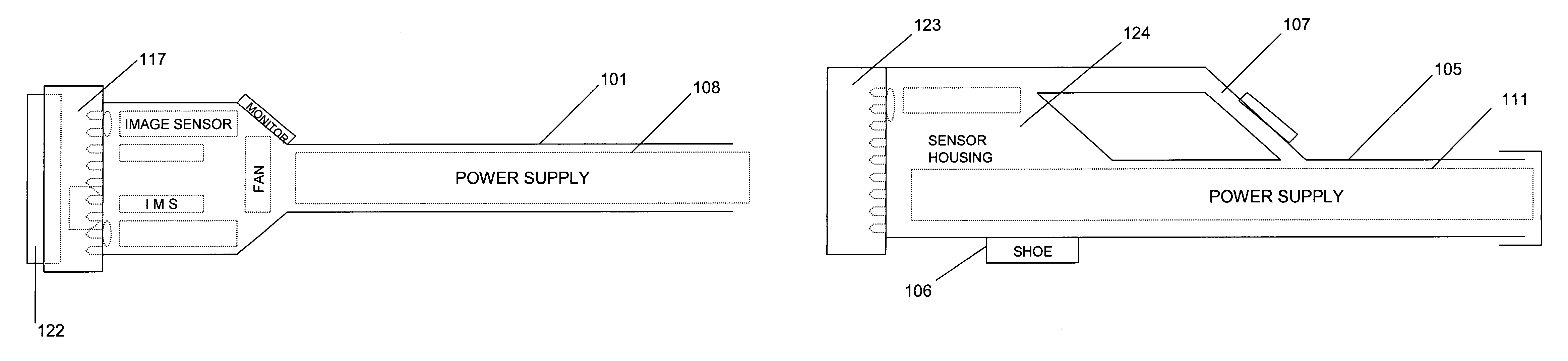
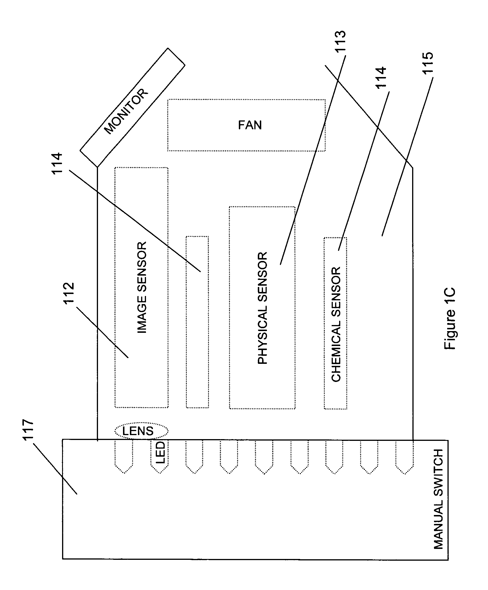
[0086]In a preferred embodiment, the device of the invention comprises a first illumination source, a second illumination source, a lens, an image sensor, a switch, a filter, a housing, and a monitor.

[0087]The first illumination source is a source of visible light illumination and the second illumination source is a source of infrared light illumination. Optionally, the candlepower of the visible light source can be varied. And, preferably, the candlepower of the first light source can be varied from 0 (off) to a maximum of at least 85,000 candlepower. Optionally, the range of infrared light illumination of the second light source is selected from 850 to 900 nanometers. And, preferably, the range of infrared light selected is further limited to include 880 nanometers.

[0088]The lens and the image sensor are positioned to permit light passing through the lens to project onto the image sensor. The image sensor has a first mode suitable for producing color images from visible light and ...

second preferred embodiment

[0095]In another preferred embodiment, a device of the invention comprises a first illumination source, a second illumination source, a lens, an image sensor, a filter, a switch, a housing, and a monitor.

[0096]The first illumination source is a source of visible light illumination. Preferably, the intensity of the first illumination source can be varied from 0 (off) to 85,000 candlepower. The second illumination source is a source of infrared light illumination selected in the range of from 850 to 900 nanometers. And preferably, the range of infrared light selected is further limited to include 880 nanometers.

[0097]The lens and the image sensor are positioned to permit light passing through the lens to project onto the image sensor, the image sensor being capable of translating visible and infrared light into an electronic signal, the filter is an infrared pass filter permitting the passage of light in the range of from 850 to 900 nanometers. The switch positions the filter such tha...

third preferred embodiment

[0099]The device includes a housing, a source of illumination and an image sensor. The housing is substantially shaped like a flashlight. The source of illumination is disposed within the housing. And, the image sensor is responsive to at last one spectral component of the source of illumination.

Other Preferred Embodiments

[0100]In another preferred embodiment, the device includes a housing which is substantially shaped like a flashlight; a source of illumination disposed within the housing; an image sensor disposed within the housing where the image sensor is responsive to at least one spectral component of the source of illumination.

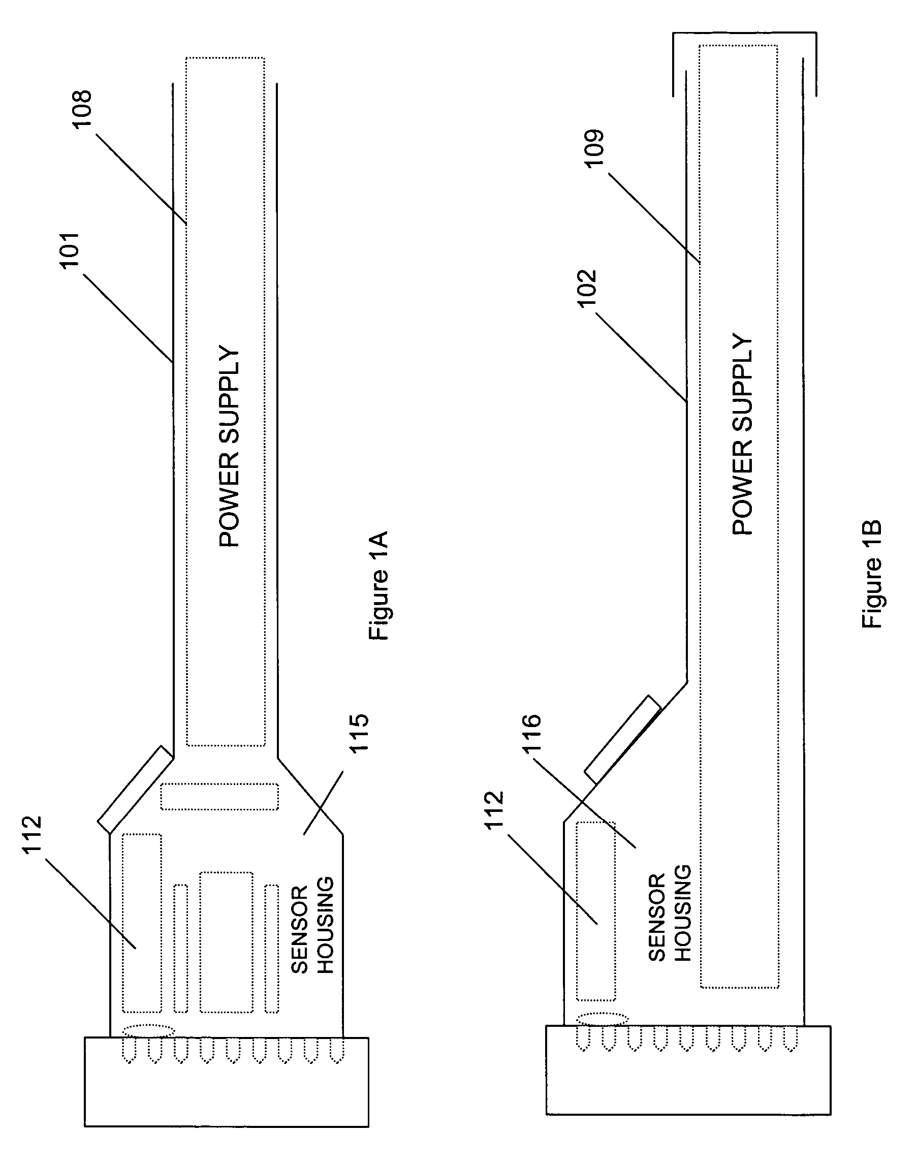
[0101]FIGS. 1A, 1B and 1E illustrate different shapes of flashlight housings. In FIG. 1A, flashlight housing 101 is suitable for carrying on a belt. In FIG. 1B, flashlight housing is shaped to allow one to set the flashlight down so that both of the user's hands are free to work. In FIG. 1E, flashlight 103 is shaped like the typical “penlight” which can...


PUM


Abstract

An improved method and apparatus for hand-held portable illumination, sensing and evidence collection is described. A uniquely configured multi-functional device selectively provides multi-purpose lighting and sensing in a hand-held portable device which is usable as a flashlight, camera and as an integrated device for evidence collection.

Description

FIELD OF THE INVENTION[0001]This invention relates to the fields of detection and collection of evidence, and more specifically to a method and apparatus for viewing an object or scene regardless of ambient lighting conditions and for detecting and collecting data from that object or scene with a single hand-held portable device.BACKGROUND OF THE INVENTION[0002]There is a widespread need for hand-held flashlights and cameras. In the fields of safety and security, there is also a need for evidence detection and collection.[0003]Law enforcement, safety and security personnel have access to an array of devices which aid them in their work. Such devices include flashlights, still and video cameras, and breathalyzers. Typically, however, due to weight or space constraints, an officer or security guard must choose the tools he or she will carry on his or her person and leave other tools behind at the station or in a vehicle. Understandably, an officer's need for safety weighs heavily on t...

Claims


Application Information

Patent Timeline
Patent Type & Authority Patents(United States)
IPC IPC(8): G03B15/03F21L4/02
CPCF21L4/027F21V23/0442F21V33/0052G03B15/03G03B17/02G03B29/00F21Y2101/02F21Y2115/10
Inventor HOWARD, MICHAELSTEINBRING, WADENELSON, KEITHBLANKS, JON W
Owner LYNK3 TECH
Why Eureka
Try Eureka