Ice skating blade

a blade and ice technology, applied in the field of ice skating blades, can solve the problems of requiring skaters to work harder to maintain balance and control, and achieve the effect of reducing the distance through which skaters “rock” on the blade, and reducing the distance between the front and rear balance points and the ice surfa

a blade and ice technology, applied in the field of ice skating blades, can solve the problems of requiring skaters to work harder to maintain balance and control, and achieve the effect of reducing the distance through which skaters “rock” on the blade, and reducing the distance between the front and rear balance points and the ice surfa

US7648146B2Inactive Publication Date: 2010-01-19TATOMIR WALLY WAYNE

Image

  • Ice skating blade
  • Ice skating blade
  • Ice skating blade

Examples


Embodiment Construction

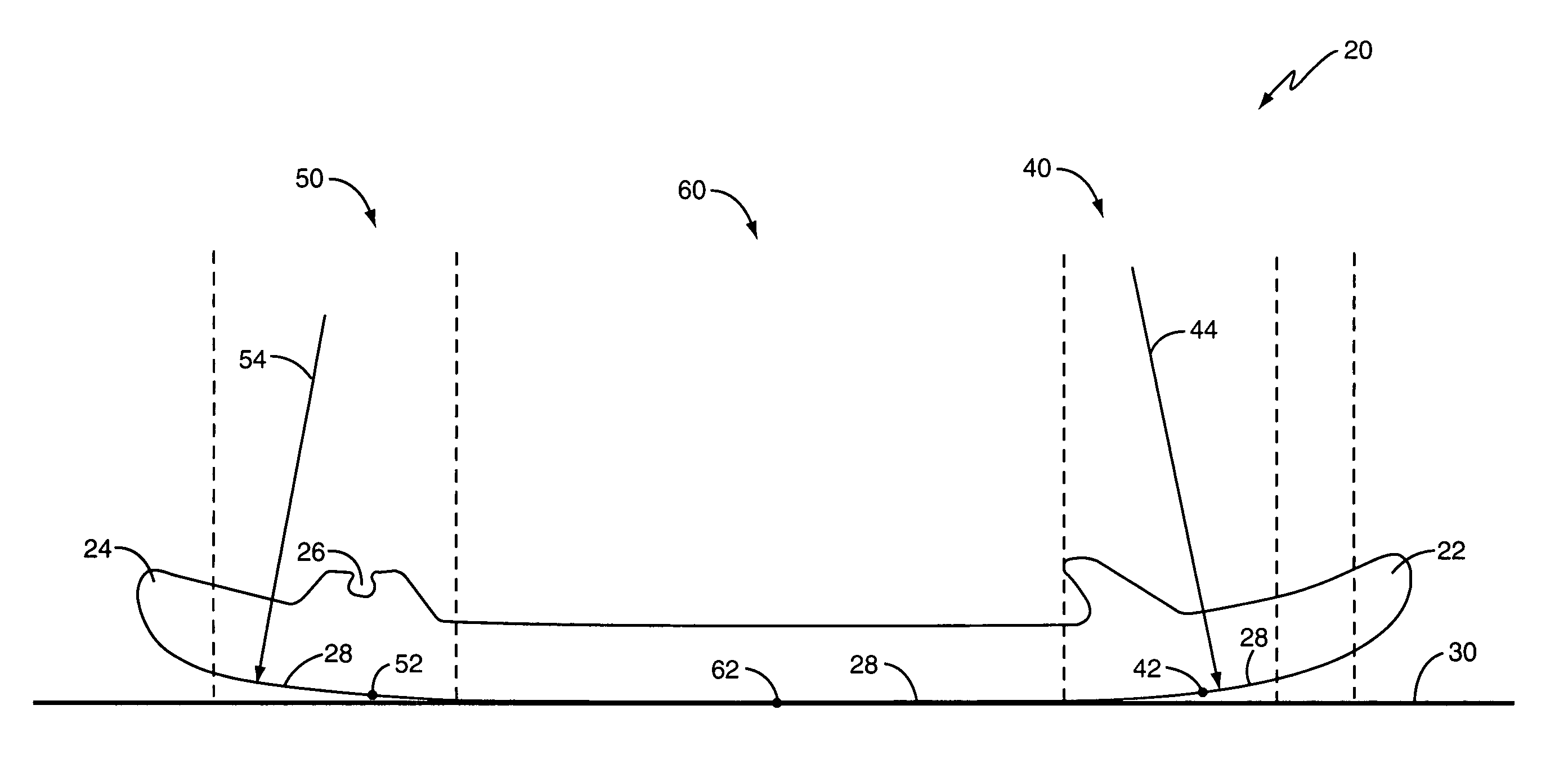
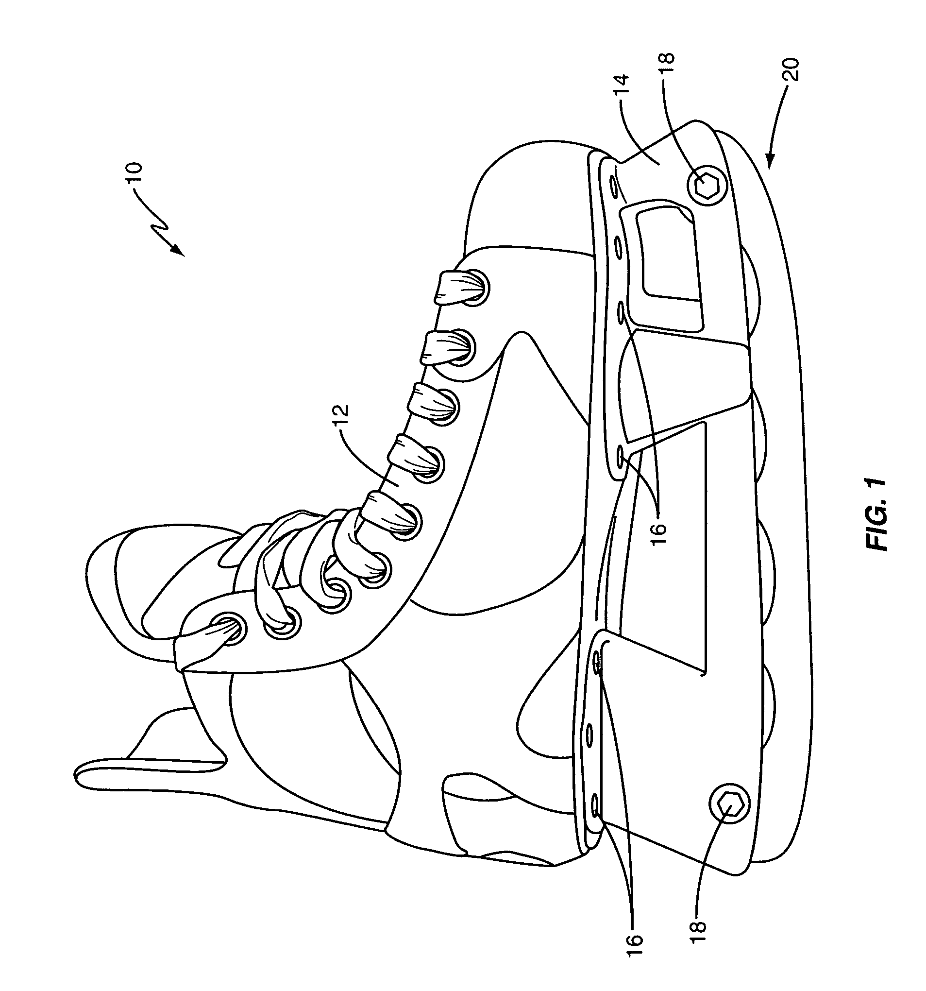
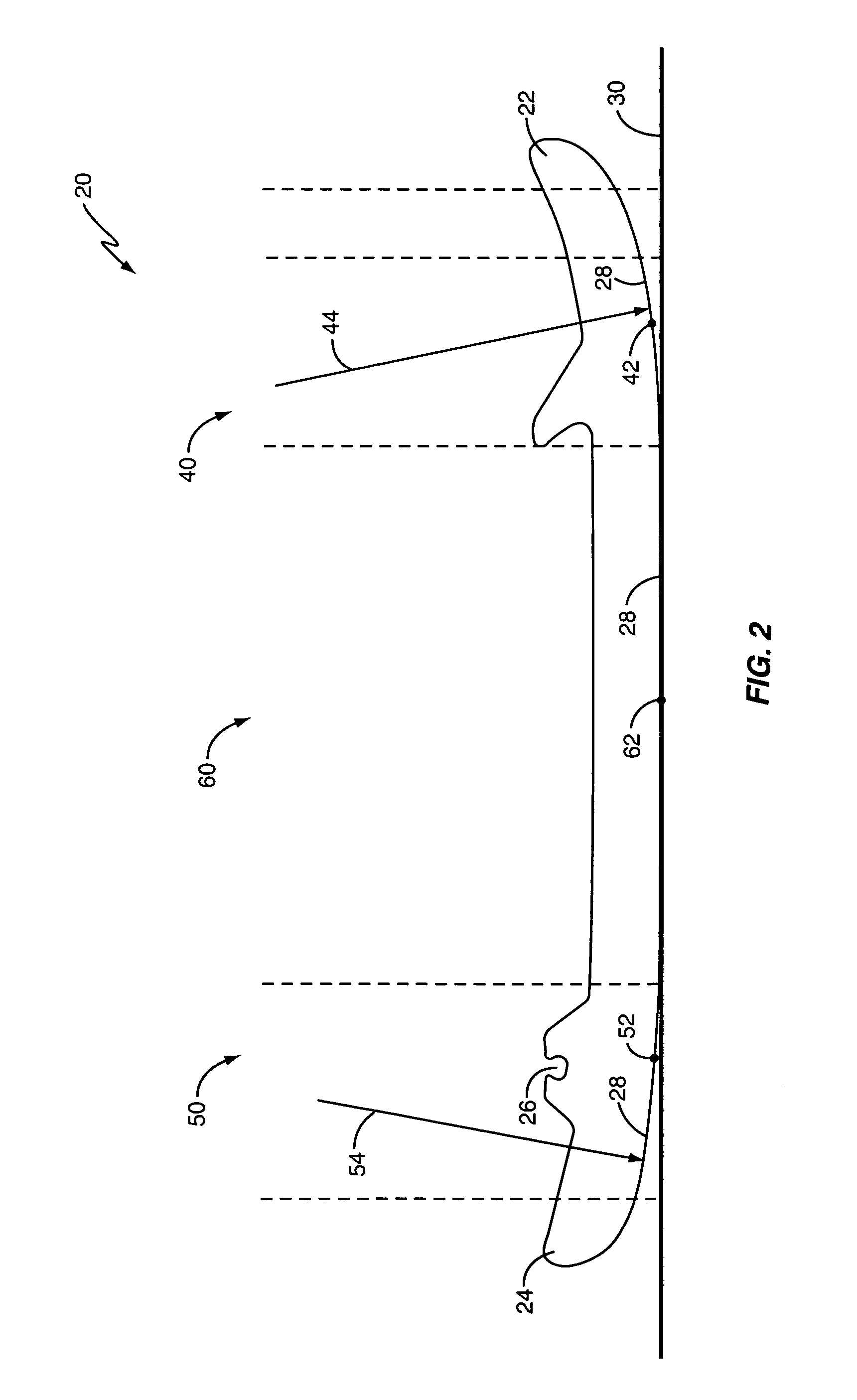
[0013]The present invention comprises a blade for ice skates and to a method for forming or shaping the blade. The present invention is particularly useful for hockey skates, which typically have a curved profile. The present invention could also be employed with other types of skates, such as skates for figure skating and speed skating. The present invention is based on the observation that there are three balance points along the bottom edge 28 of the blade, referred to herein as the front balance point 42, the center balance point 62, and the rear balance point 52. The balance points 42, 52, 62 are points on the blade over which the skater's center of gravity lies when the skater performs various movements on an ice surface. The blade according to the present invention is shaped to maintain critical vertical distances between the three balance points 42, 52, 62, and a line that runs tangentially to the center balance point 52. One result is that the front and rear balance points ...


PUM


Abstract

A skate blade has a front curved section having a front balance point, a rear curved section having a rear balance point, and a middle section having a center balance point. Each balance point is a point on the skate blade over which a skater's center of gravity lies depending on the skater's position. The skate blade is shaped such that the middle section is substantially flat. Additionally, the blade is shaped such that more of the blade extends away from a blade holder at the rear balance point than at the front balance point.

Description

RELATED APPLICATIONS[0001]This application claims priority under 35 U.S.C. §119(e) from U.S. provisional Application No. 60 / 659,107 filed on Mar. 8, 2005, which is incorporated herein by reference in its entirety.BACKGROUND[0002]The present invention relates generally to an ice skating blade, and more particularly to an ice skating blade shaped to improve skater performance, balance, and control.[0003]Ice skating is a favorite activity for many people. Skaters usually glide along an ice surface, periodically make turns, transition between forward and backward skating, and quickly accelerate and decelerate at various times. Each of these actions requires that the skater maintain balance and control his or her movements.[0004]The shape of conventional ice skating blades or runners, however, forces the skater to work harder to maintain balance and control. This is because most conventional blades are curved from the toe (i.e., front) of the blade to the heel (i.e., back) of the blade. ...

Claims


Application Information

Patent Timeline
19 Jan 2010
Publication
US7648146B2
IPC
A63C3/00
CPC
A63C1/32; A63C1/42
Inventors
TATOMIR, WALLY WAYNE