Connector for joining with agricultural drip tape

a technology for connecting wires and drip tapes, applied in the direction of hose connections, pipe elements, pipe connection arrangements, etc., can solve problems such as destroying connections, and achieve the effect of consistent reliable sealing

Inactive Publication Date: 2010-01-19
ANDROS MATTHEW J
View PDF18 Cites 18 Cited by
  • Summary
  • Abstract
  • Description
  • Claims
  • Application Information

AI Technical Summary

Benefits of technology

[0010]In accordance with this invention, the connector includes a rigid tubular body that terminates at its free end to a tapered enlargement over which the free end of the drip tape must be pressed and held. The drip tape makes a sealing contact against a circular portion of the enlargement. A male thread is adjacent to a rigid tubular section of the body and has a single entry. An assembly nut having a single entry female thread for engagement with the male thread on the tubular body is first positioned to circumferentially enclose the free end of the drip tape. The nut includes a tapered surface having an internal diameter smaller than the largest diameter of the enlargement. This permits the free end portion of the tape to fit between the tapered section and to be held there.
[0011]Because both the male body threads and nut threads are single entry, there is only one rotational position of the nut relative to the tubular body at which these threads can start to join. It is important to this invention that the nut must be tightened far enough to hold the tape to the tube and even to press it along slightly. Opposed to this consideration is that over-tightening can cause the nut to cut the tape thereby destroying the connection.
[0012]According to this invention, the tubular body and the nut are provided with body indicia and nut indicia, respectively, which depending upon the wall thickness and physical properties of the tape, will dictate to the assembler the correct selection of a particular nut indicia for alignment with the body indicia to form a consistently reliable seal. The relative positions of the indicia will have, by previous testing, been determined for the particular type drip tape to be joined. Thus, the assembler, by knowing the wall thickness and characteristic properties of the tape, and utilizing the test information, will, after hand tightening the nut to advance resistance, tool tighten the nut further until the test determined angular displacement of the nut indicia is positioned with respect to the body indicia.

Problems solved by technology

Opposed to this consideration is that over-tightening can cause the nut to cut the tape thereby destroying the connection.

Method used


Image

  • Connector for joining with agricultural drip tape
  • Connector for joining with agricultural drip tape
  • Connector for joining with agricultural drip tape

Examples


Embodiment Construction

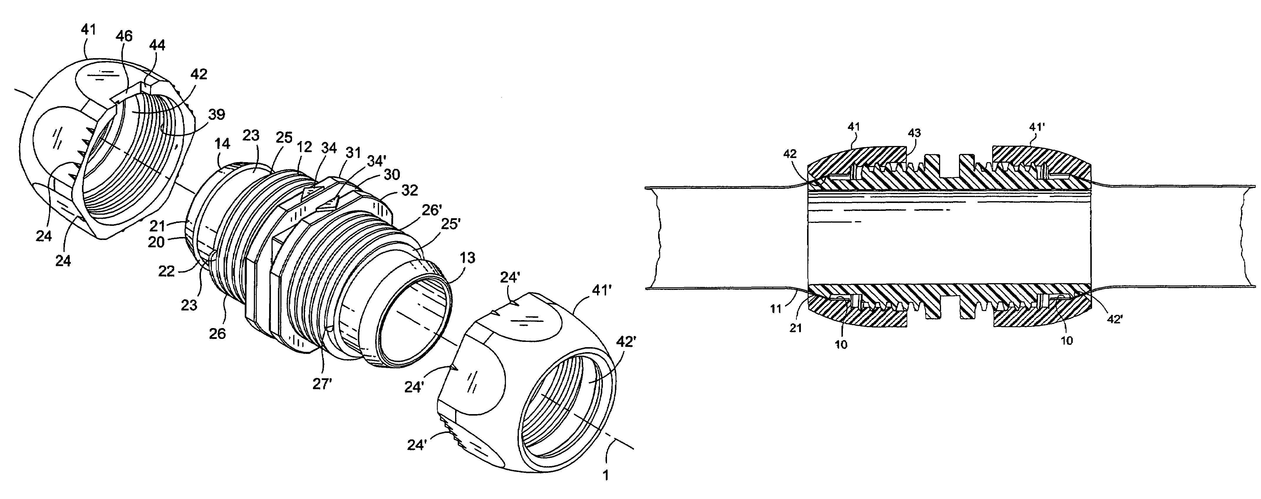
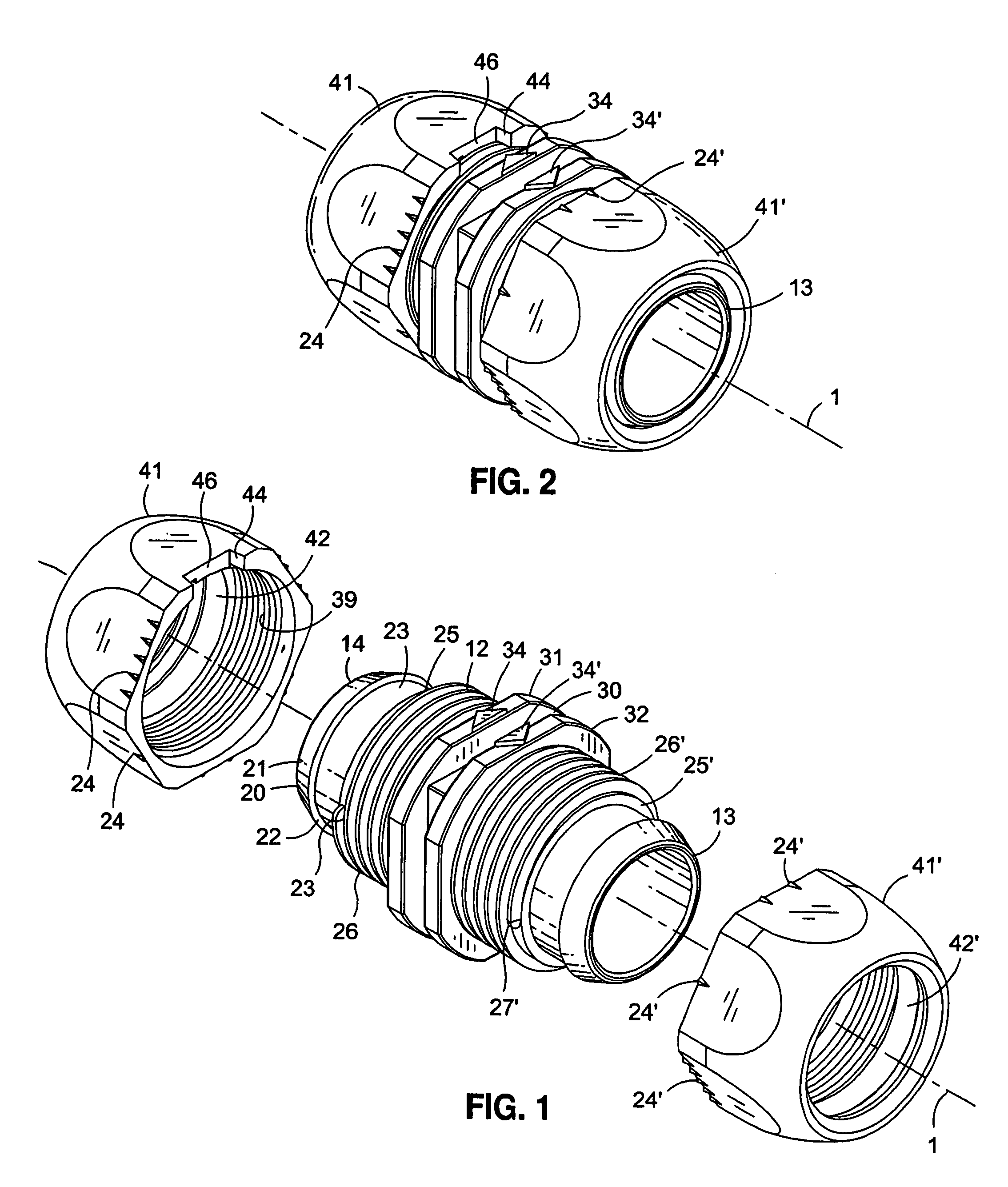
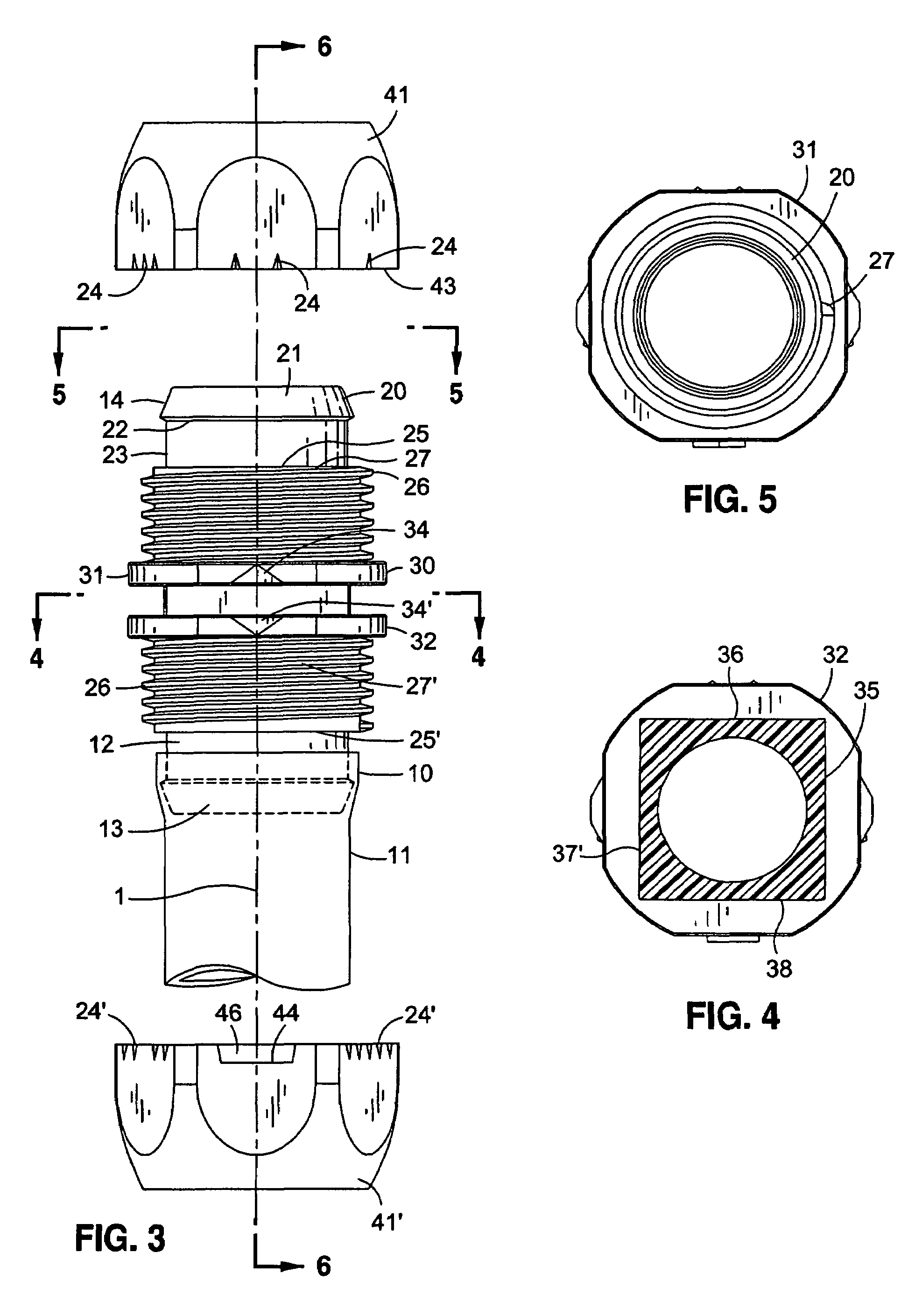
[0021]FIG. 1 illustrates in perspective an exploded view of the tubular connector for joining drip tape and FIG. 2 illustrates in perspective the assembly of the various elements shown in FIG. 1. The purpose of this invention is to reliably join the free end 10 of a length 11 of irrigation drip tape to a tubular body 12 as can be seen by reference to FIG. 3. This connector may, for example be a rigid tubular structure which functions as a splice or coupler to join two such tape lengths, or it may be a projection from a manifold (not shown) to which the tape is to be connected.

[0022]For convenience in disclosure, tubular body 12 is shown in FIGS. 1 and 3 in its most common double-ended configuration, which is duplicated at each of its ends 13 and 14. End 14 will be described in detail, recognizing that end 13 and 14 are identical.

[0023]As can be seen in FIG. 1, tubular body 12 has a central axis 1 about which at the free end of 14 there is formed an encircling enlargement 20 with a f...


PUM

PropertyMeasurementUnit
diameteraaaaaaaaaa
mechanical pressureaaaaaaaaaa
strengthaaaaaaaaaa

Abstract

A connector for joining agricultural drip tape. The connector includes a rigid tubular body having a tapered trust conical enlargement at its free end over which the free end of the drip tape is pressed and held by an assembly nut having a single entry female thread that threadably engages the tubular body male threads by a pre-determined angular advance of the assembly nut. The environment of use for agricultural drip tape is one of debris and mud consequently; the assembly nut contains a wiper window opening through which debris and mud are expelled from the connection as the assembly nut advances axially along the threads of the tubular body. Indicia on both the assembly nut and on the tubular body may be relatively positioned depending upon the thickness of the tape to form a consistently reliable seal.

Description

FIELD OF THE INVENTION[0001]A connector to which the free end of a length of drip tape can readily and releasably be joined.BACKGROUND OF THE INVENTION[0002]In this specification the term “drip tape” will be used to describe this precise product and also any other type of drip conduit, including those in round form more properly described as tubes or tubing. These terms are used interchangeably in this specification. All these products are made of organic plastic material, usually with thin walls. They include in their length a series of spaced-apart emitters.[0003]Emitters are passages through the walls from the lumen of the tape to its outside. They permit controlled flow of water through the wall at their specific places along the length of the tape and allow water to flow through them at a limited rate into the soil on or in which the tape is laid or implanted. These provide for application of water in known amounts at precise locations relative to the crop, plant, or tree, ther...

Claims


Application Information

Patent Timeline
Patent Type & Authority Patents(United States)
IPC IPC(8): F16L33/00
CPCF16L33/223
Inventor ANDROS, MATTHEW J.
Owner ANDROS MATTHEW J
Why Eureka
Try Eureka