
Low profile probe having improved mechanical scrub and reduced contact inductance

a low-profile, probe technology, applied in the field of probes, can solve the problems of unsurprising existence of some such limit, inability to deposition an unlimited number of layers, and micro-fabrication approaches that typically impose an overall height limit on fabricated probes, etc., to achieve advantageously reduce the inductance of the probe, improve the scrub performance, and increase the lateral scrub motion

Active Publication Date: 2010-01-19
MICRO PROBE
View PDF17 Cites 32 Cited by
  • Summary
  • Abstract
  • Description
  • Claims
  • Application Information

AI Technical Summary

Benefits of technology

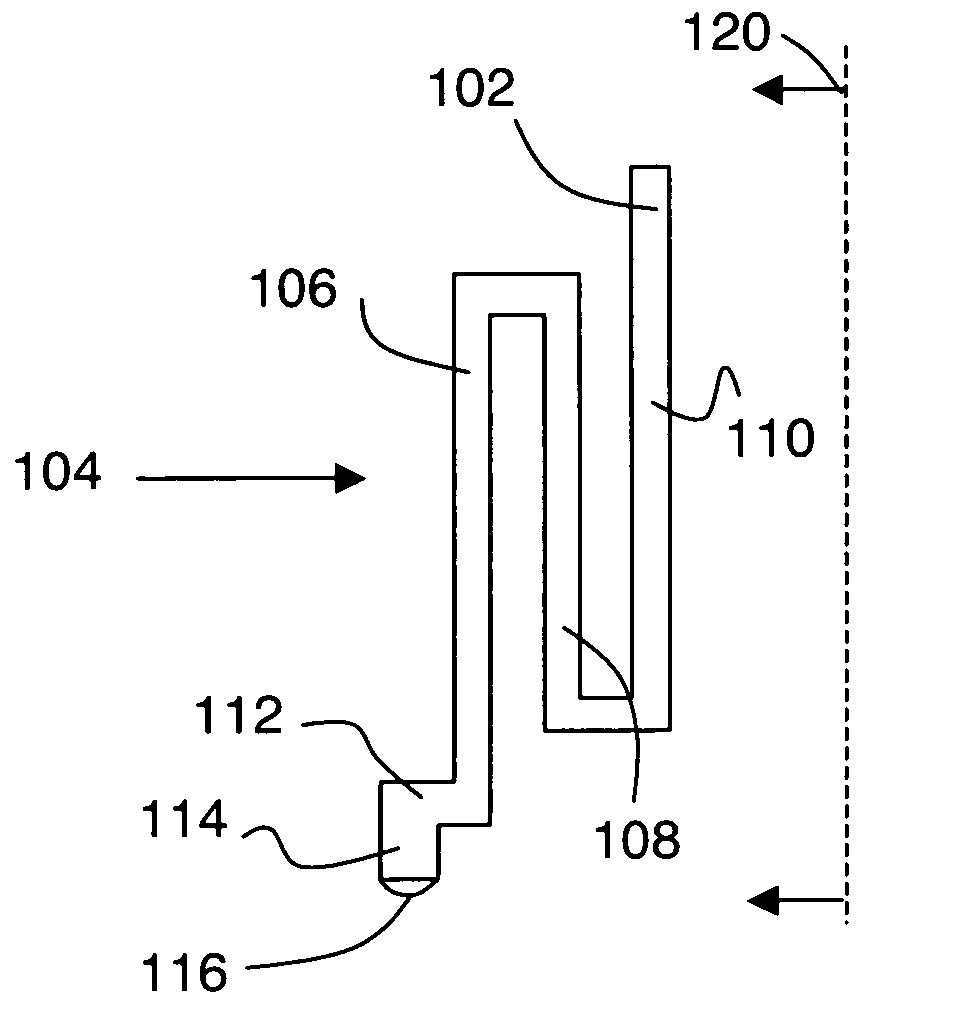
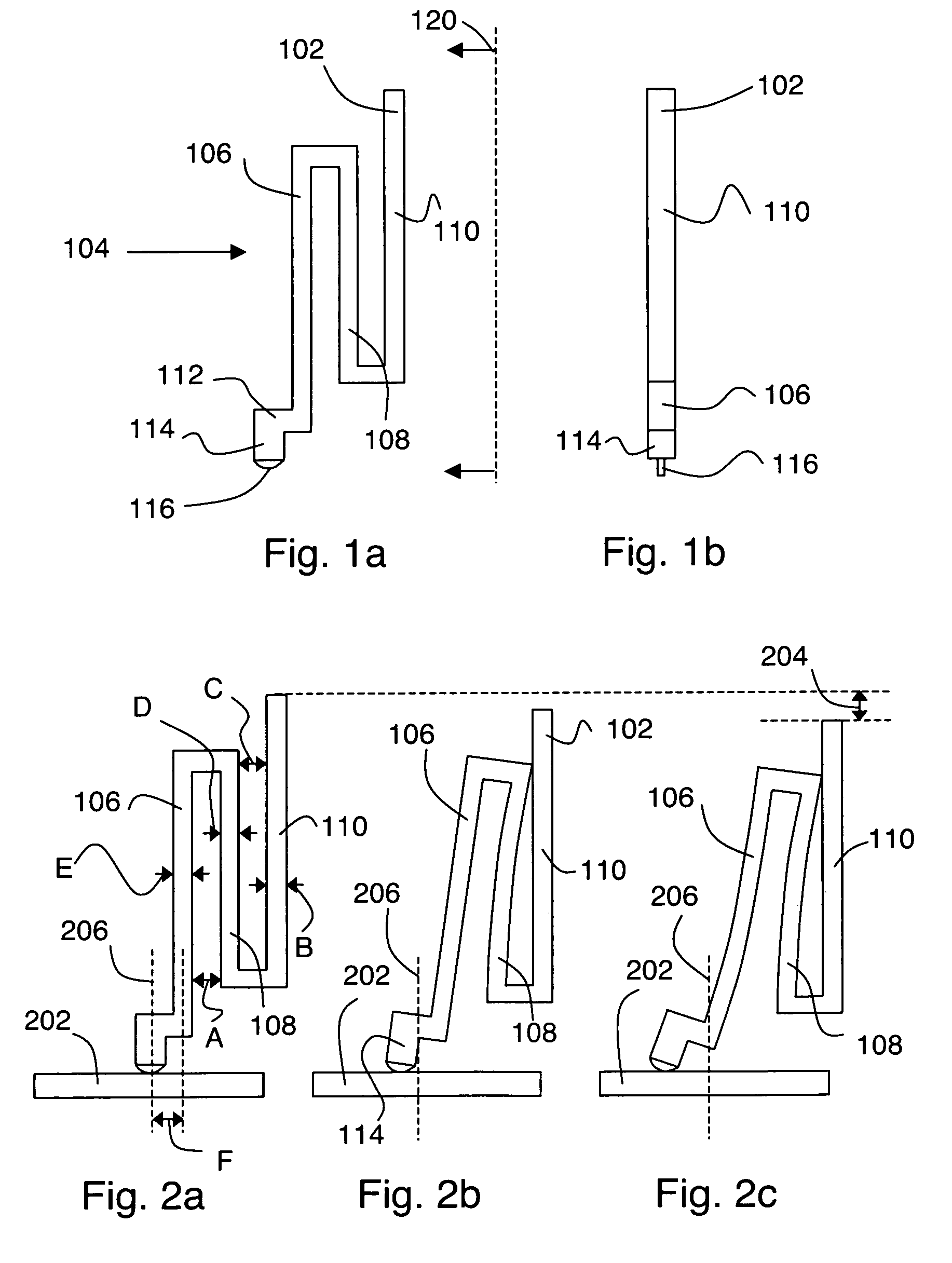
[0008]According to the invention, a vertically folded probe can provide improved scrub performance in cases where the probe height is limited. More specifically, such a probe includes a base and a tip, and an arm extending from the base to the tip as a single continuous member. The probe arm is vertically folded, such that it includes three or more vertical arm portions. The vertical arm portions have substantial vertical overlap, and are laterally displaced from each other. When such a probe is vertically brought down onto a device under test, the probe deforms. During probe deformation, at least two of the vertical arm portions come into contact with each other. Such contact between the arm portions can advantageously increase the lateral scrub motion at the probe tip, and can also advantageously reduce the probe inductance.

Problems solved by technology

Micro-fabrication approaches typically impose an overall height limit on the fabricated probe.
The existence of some such limit is unsurprising, since deposition of an unlimited number of layers is unlikely to be practical.
However, we have found that such scaling of known probe geometries to comply with the height limit of probe micro-fabrication tends to provide probes having unfavorable performance characteristics.
In particular, it is difficult to obtain sufficient lateral scrub motion from conventional probe geometries scaled to comply with a height limit on the order of 0.8 mm.

Method used


Image

  • Low profile probe having improved mechanical scrub and reduced contact inductance
  • Low profile probe having improved mechanical scrub and reduced contact inductance
  • Low profile probe having improved mechanical scrub and reduced contact inductance

Examples


Embodiment Construction

[0015]FIGS. 1a-b show two views of a probe according to an embodiment of the invention. The probe includes a probe base 102, a probe tip 114, and an arm 104 extending from probe base 102 to probe tip 114 as a continuous member. Arm 104 includes three or more vertical arm portions, which in this example are labeled as 106, 108, and 110. The vertical arm portions are substantially parallel to a direction of relative motion between probe and DUT as contact is made. The vertical arm portions are laterally displaced from each other, as shown. Finally, the vertical arm portions have a substantial vertical overlap with each other, also as shown. The net effect of these geometrical constraints is to ensure that arm 104 is folded vertically from base 102 to tip 114, as opposed to being folded horizontally between base 102 and tip 114. FIG. 1b shows a view of the probe of FIG. 1a as seen from view 120.

[0016]Optionally, probe arm 104 can include a lateral termination 112, on which probe tip 11...


PUM


Abstract

A vertically folded probe is provided that can provide improved scrub performance in cases where the probe height is limited. More specifically, such a probe includes a base and a tip, and an arm extending from the base to the tip as a single continuous member. The probe arm is vertically folded, such that it includes three or more vertical arm portions. The vertical arm portions have substantial vertical overlap, and are laterally displaced from each other. When such a probe is vertically brought down onto a device under test, the probe deforms. During probe deformation, at least two of the vertical arm portions come into contact with each other. Such contact between the arm portions can advantageously increase the lateral scrub motion at the probe tip, and can also advantageously reduce the probe inductance.

Description

CROSS REFERENCE TO RELATED APPLICATIONS[0001]This application claims the benefit of U.S. provisional application 60 / 748,438, filed on Dec. 7, 2005, entitled “Micro-Fabricated Low Profile Probe”, and hereby incorporated by reference in its entirety.FIELD OF THE INVENTION[0002]The present invention relates to probes for making electrical contact to a device under test (DUT).BACKGROUND[0003]Probes for making electrical contact to a device under test (DUT) are typically resilient devices that deform in a controllable manner in use. Probe deformation can perform various functions, such as providing a suitable scrub motion between probe tip and contact pad to facilitate making a reliable electrical contact. The shape of a probe has a significant effect on its deformation properties, and accordingly many kind of probe shapes have been considered in the art. Representative examples of known probe shapes include U.S. Pat. Nos. 6,707,311, 6,482,013, 6,278,284, 5,832,601, 6,956,389, 6,677,245,...

Claims


Application Information

Patent Timeline
IPC IPC(8): G01R1/06
CPCG01R1/06733
Inventor KISTER, JANUARY
Owner MICRO PROBE
Learn More