Repair apparatus for a nuclear reactor shroud

a technology for repairing apparatus and nuclear reactor, which is applied in the direction of nuclear elements, manufacturing tools, greenhouse gas reduction, etc., can solve the problems of reducing corrosion resistance, reducing corrosion resistance, and reducing the grain structure of chromium, so as to reduce the risk of intergranular stress corrosion cracking, the effect of reducing the risk of intergranular stress corrosion

Inactive Publication Date: 2010-01-19
GENERAL ELECTRIC CO
View PDF27 Cites 5 Cited by
  • Summary
  • Abstract
  • Description
  • Claims
  • Application Information

AI Technical Summary

Benefits of technology

[0005]In another preferred embodiment of the present invention, there is provided a repair apparatus for repairing a shroud in a nuclear reactor pressure vessel including a core shroud defining an annulus with the reactor pressure vessel, a core shroud support cylinder and plate, shroud cylinders defining the core shroud, the repair apparatus comprising; an upper support assembly for securement to the shroud; a tie rod secured at an upper end thereof to the upper support assembly and extending in the annulus; a lower stabilizer assembly attached to each tie rod with a wedge bearing against the vessel shell enabling alignment of the tie rod to pass closely adjacent to the lower shroud cylinder; a lower end of the tie rod extending through an opening in the core shroud support plate; and an anchor attached to the lower end of the tie rod and the core shroud support cylinder enabling a compressive load path through the shroud cylinders substantially without loading the shroud support plate.

Problems solved by technology

It additionally locally sensitizes the stainless steel, which depletes the grain structure of chromium and reduces corrosion resistance.
These factors, combined with the BWR reactor coolant environment, make the weld heat affected zones susceptible to intergranular stress corrosion cracking (IGSCC), observed in many BWR shrouds.
The cracking impairs the structural integrity of the shroud.
These anchorage arrangements are not feasible where the structural integrity of the shroud support plate has also been impaired by IGSCC cracking, such that it cannot support the additional localized loading for the required tie rod anchorage at the bottom of the shroud.

Method used


Image

  • Repair apparatus for a nuclear reactor shroud
  • Repair apparatus for a nuclear reactor shroud
  • Repair apparatus for a nuclear reactor shroud

Examples


Embodiment Construction

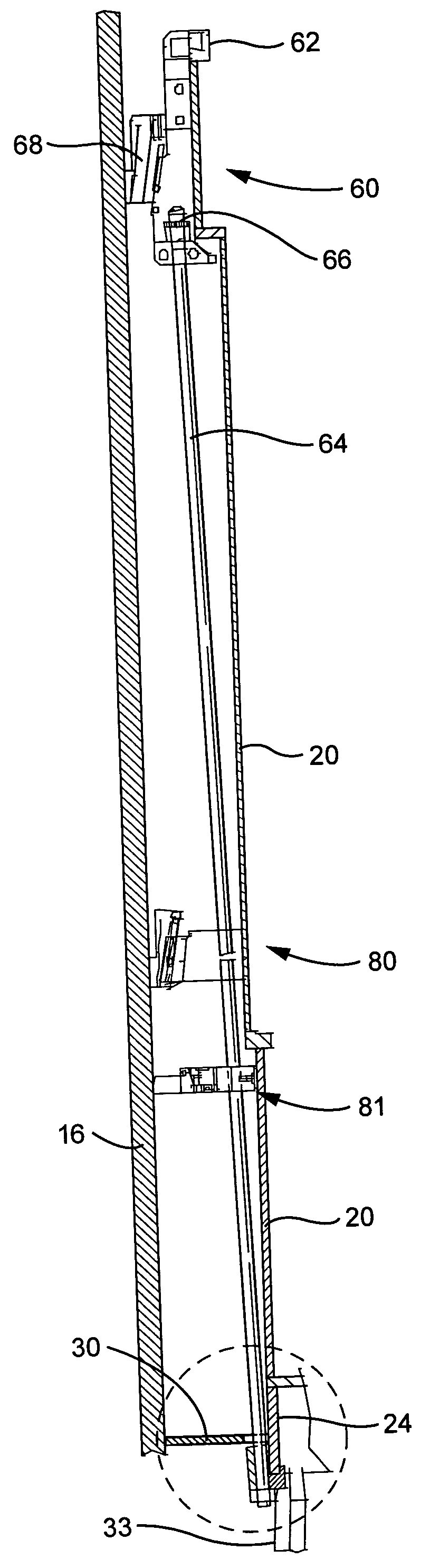
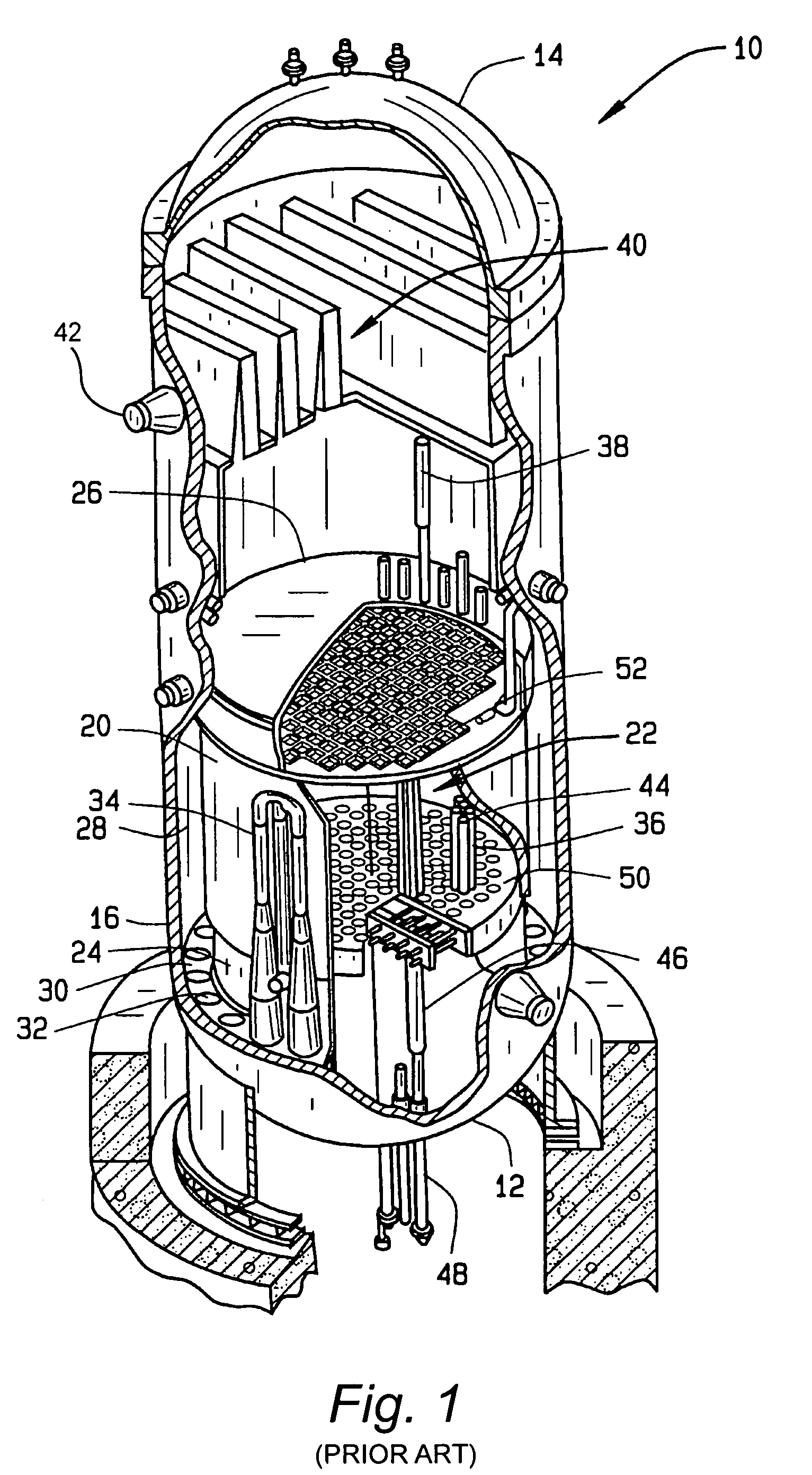
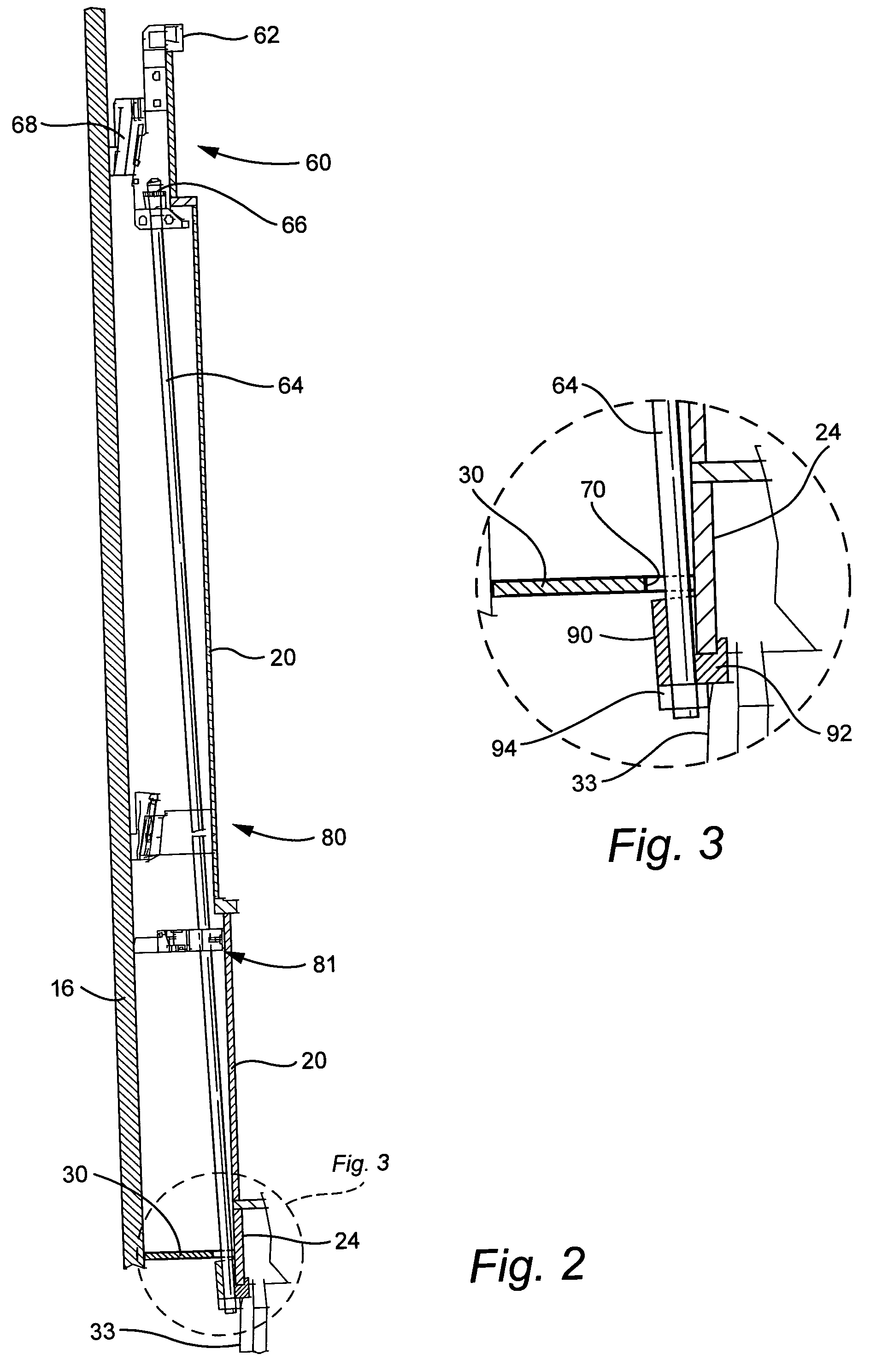
[0010]FIG. 1 is a sectional view, with parts cut away in cross section, of a boiling water nuclear reactor pressure vessel (RPV) 10. RPV 10 has a generally cylindrical shape and is closed at one end by a bottom head 12 and at its upper end by a removable top head 14. An RPV shell 16 extends from bottom head 12 to top head 14. A cylindrically shaped core shroud 20 surrounds a reactor core 22. Shroud 20 is supported at one end by a lower shroud support cylinder 24 and includes a removable shroud head 26 at its upper end. An annulus 28 is formed between shroud 20 and RPV shell 16. Shroud support plate 30, which has a flat ring shape, extends between shroud support cylinder 24 and RPV shell 16. The shroud support cylinder 24 is also attached to the RPV bottom head 12 by a plurality of vertical stilts 33 located at substantially equally spaced positions about the shroud support cylinder 24, shown on FIG. 2. Loads required to support core shroud 20 and reactor core 22 are transmitted by s...


PUM

PropertyMeasurementUnit
compressiveaaaaaaaaaa
residual stressesaaaaaaaaaa
grain structureaaaaaaaaaa

Abstract

The tie rod repair apparatus includes a tie rod secured at its upper end to the shroud flange at the top of the shroud. The lower end of the tie rod passes through an opening in the shroud support plate without imposing a load on the plate. The lower end of the tie rod is anchored to the lower end of the core shroud support cylinder such that the compressive load path exerted by the tie rod to restrain the cracked shroud passes directly through the shroud support cylinder and the assembly of shroud cylinders bypassing the shroud support plate.

Description

[0001]The present invention relates to repair apparatus for the core shroud of a boiling water nuclear reactor and particularly relates to a tie rod repair which locates the compressive load path exerted by the tie rods to restrain a cracked shroud directly through the shroud support cylinder and shroud cylinders without applying additional load to the shroud support plate.BACKGROUND OF THE INVENTION[0002]The core shroud in boiling water reactors (BWR) supports and locates the reactor core within the reactor pressure vessel (RPV), and forms the flow partition for the reactor core coolant. It is constructed of a number of stainless steel circular rings and cylindrical rolled plate sections, joined at their ends with circumferential welds. The welding introduces residual stresses in the weld heat affected zones. It additionally locally sensitizes the stainless steel, which depletes the grain structure of chromium and reduces corrosion resistance. These factors, combined with the BWR r...

Claims


Application Information

Patent Timeline
Patent Type & Authority Patents(United States)
IPC IPC(8): G21C9/00
CPCG21C13/02G21C19/00G21C19/207G21Y2002/201Y10T29/53952G21Y2004/301G21Y2004/504Y02E30/40G21Y2002/304Y02E30/30
Inventor ERBES, JOHN GEDDES
Owner GENERAL ELECTRIC CO
Why Eureka
Try Eureka