Terminal component

Inactive Publication Date: 2010-01-26
WAGO VERW GMBH
View PDF13 Cites 37 Cited by
  • Summary
  • Abstract
  • Description
  • Claims
  • Application Information

AI Technical Summary

Benefits of technology

[0007]Against this background, the object of the present invention is to further reduce the width of clamping components in the direction of the spring excursion of the clamping spring.

Problems solved by technology

However, this is only possible by virtue of the fact that the bearing limb of the clamping spring itself forms a wall of the conductor insertion channel, along which the conductor end is guided.

Method used


Image

  • Terminal component
  • Terminal component
  • Terminal component

Examples


Embodiment Construction

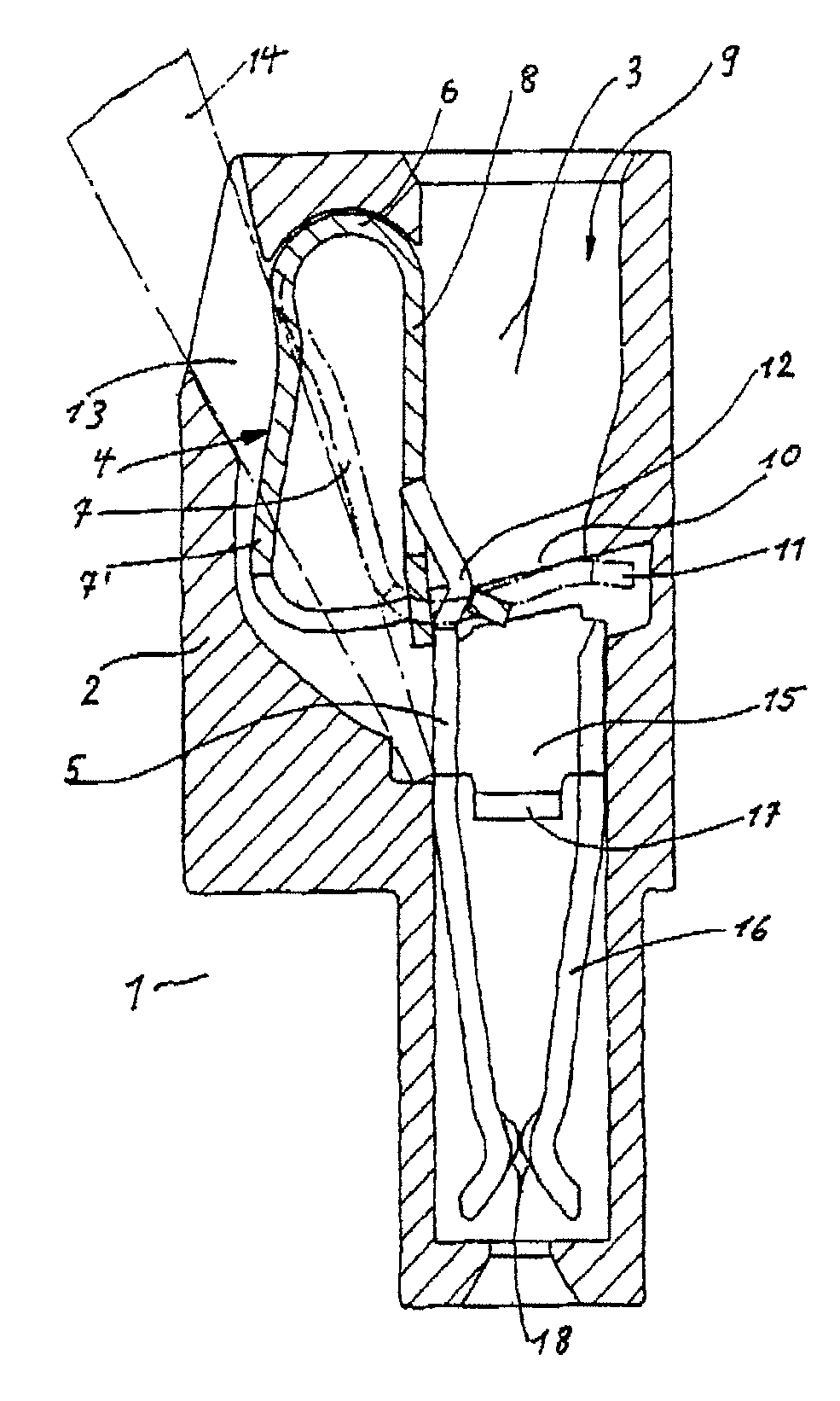
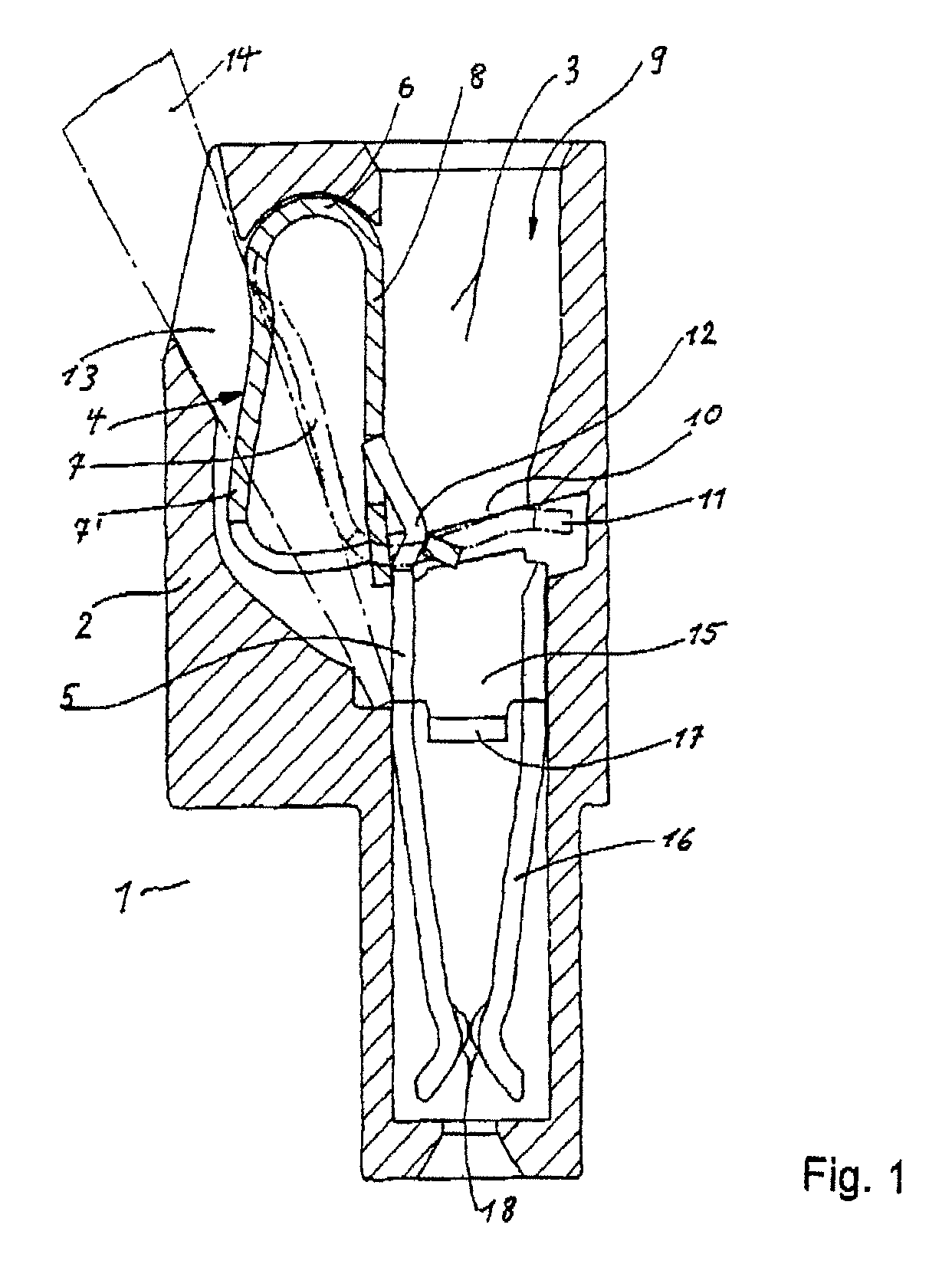
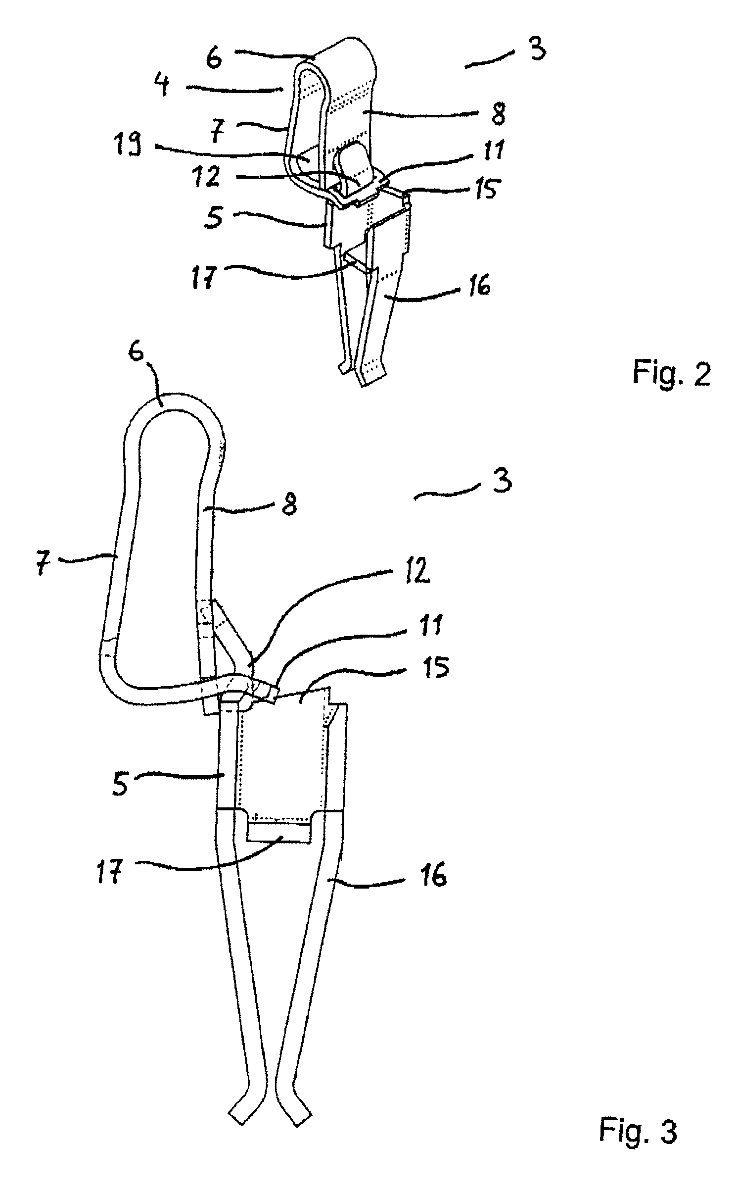
[0030]FIG. 1 shows a terminal component 1 as a detail and in cross section. The terminal component 1 has an insulating housing 2, which is formed in a manner known per se from an electrically insulating material, in particular plastic material. At least one spring clamping connection 3 is arranged in the insulating housing 2 and is formed from a clamping spring 4 and a busbar 5. The clamping spring 4 is formed from sheet spring steel and has a spring bow 6, whose first end is adjoined by a clamping limb 7 and whose second end is adjoined by a bearing limb 8. The clamping limb 7 is bent approximately at right angles and has, in its section 10 extending substantially transversely with respect to the direction of a conductor insertion channel 9, a window cutout, through which one end of the busbar 5 is plugged. That end of the busbar 5 which is plugged through the window cutout is bent in the direction of the bearing limb 8 and plugged into an opening in the bearing limb 8. It can be s...


PUM


Abstract

The invention describes a terminal component (1) with an insulating housing (2) and at least one spring-force clamping connection (3), which has a bent clamping spring (4), formed from sheet spring steel, with bearing limbs (8) and clamping limbs (7), which are connected to one another via a spring bow (6), a busbar (5), which is inserted into the clamping limb (7) and bears against the bearing limb (8), and a conductor insertion channel (9), which is formed in the insulating housing (2) and extends from the rear spring bow (6) of the clamping spring (4) along the bearing limb (8) at least as far as the busbar (5). The wall, which is formed from the insulating housing (2), of the conductor insertion channel (9) is partially interrupted. That end of the busbar (5) which bears against the bearing limb (8) runs obliquely with respect to the bearing limb (8) and forms a funnel of the conductor insertion channel (9). The bearing limb (8) of the clamping spring (4) forms, in the interrupted part of the insulating housing (2), together with the busbar (5), a wall of the conductor insertion channel (9).

Description

FIELD OF THE INVENTION[0001]The invention relates to a terminal component with an insulating housing and at least one spring-force clamping connection, which has a bent clamping spring, formed from sheet spring steel, with bearing limbs and clamping limbs, which are connected to one another via a spring bow, a busbar, which is inserted into the clamping limb and bears against the bearing limb, and a conductor insertion channel, which is formed in the insulating housing and extends from the rear spring bow of the clamping spring along the bearing limb at least as far as the busbar.BACKGROUND OF THE INVENTION[0002]Such clamping components are known as connecting terminals for electrical conductors from DE 197 11 051 A1. The conductors are inserted into the conductor insertion channel via the spring bow through an aperture in the clamping limb into an area of the conductor insertion channel beneath the clamping spring. In this case, the conductor insertion channel is formed by a turn i...

Claims


Application Information

Patent Timeline
IPC IPC(8): H01R4/24
CPCH01R13/112H01R4/4827H01R4/48275H01R13/52
Inventor KOELLMANN, HANS-JOSEF
Owner WAGO VERW GMBH
Why Eureka
Try Eureka