

Detachable hand tool
- Summary
- Abstract
- Description
- Claims
- Application Information
AI Technical Summary
Benefits of technology
Problems solved by technology
Method used
Image

Examples
Embodiment Construction
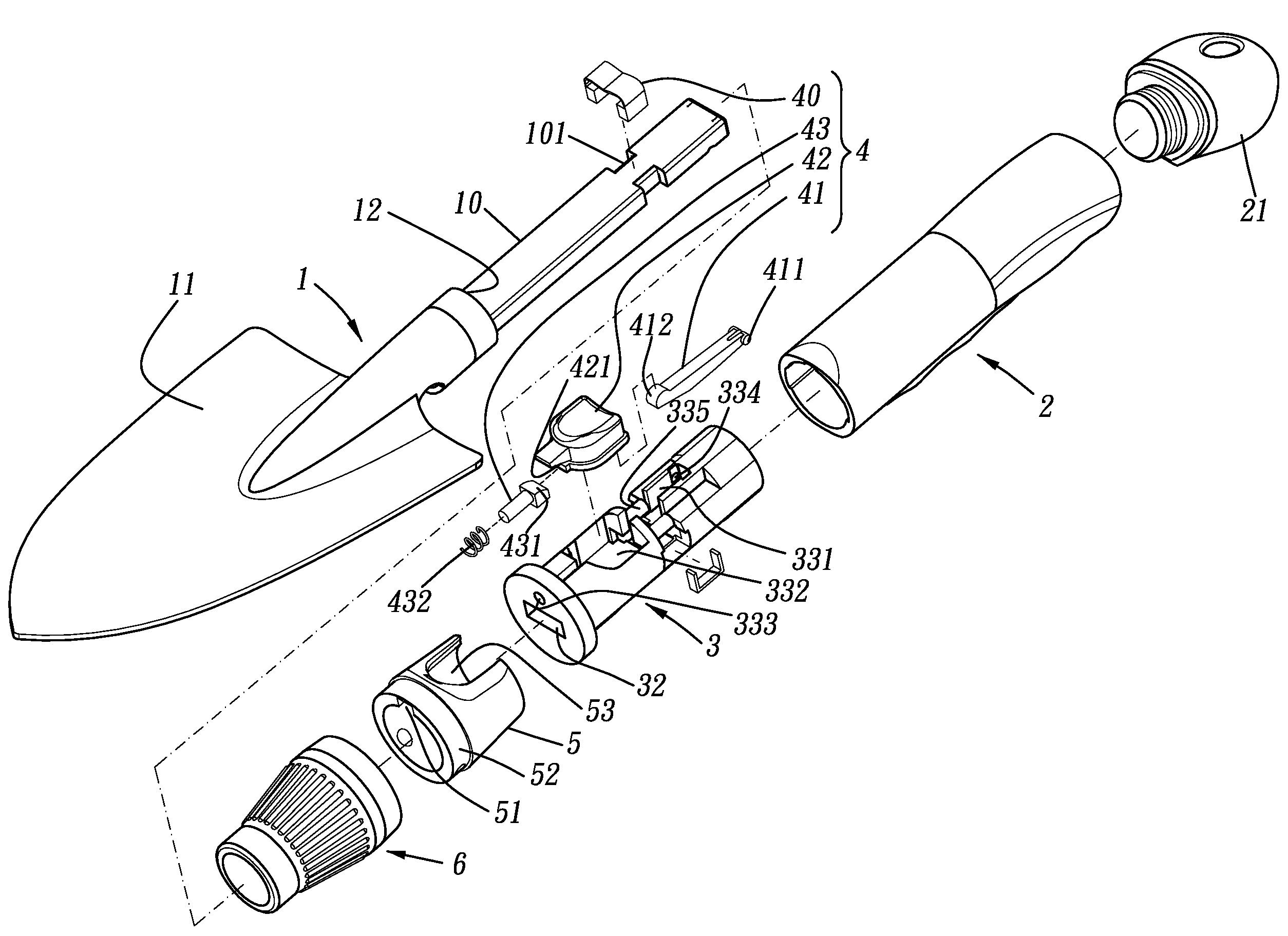
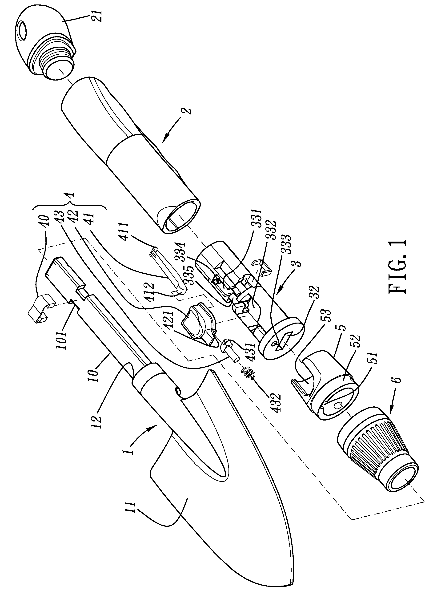
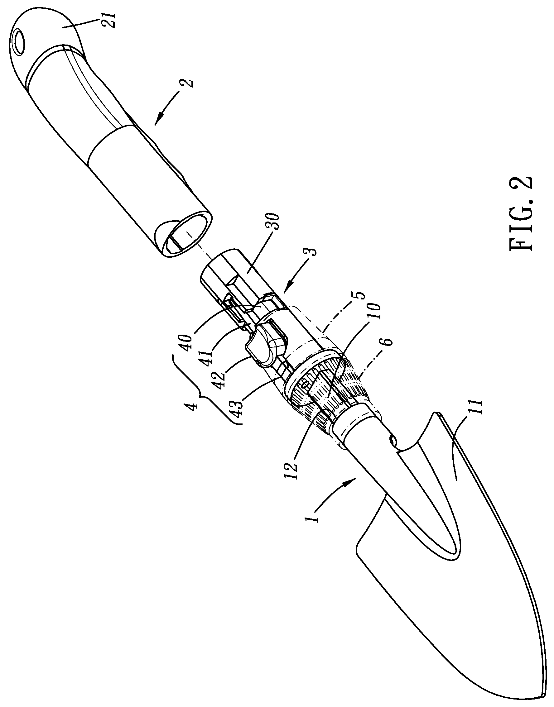
[0023]Referring to the drawings and initially to FIGS. 1-3, a detachable hand tool in accordance with the present invention comprises a handle 2, a spindle 3 partially received in one end of the handle 2, a cap 21 partially received in the other end of the handle 2, a casing 5 sleeved on the spindle 3, a head 6 sleeved on the casing 5, a tool driver 1 partially and detachably mounted in the spindle 3, and a control assembly 4 mounted on the spindle 3 for detaching the tool driver 1.
[0024]The spindle 3 has a first end partially received in the handle 2 and a second end partially received in the casing 5. The first end of the spindle 3 is opposite to the second end of the spindle 3. The spindle 3 has a groove 32 longitudinally defined therein. The spindle 3 has a hole 333 longitudinally defined therein and being adjacent to the groove 32. The spindle 3 has a first recess 331 laterally defined therein and being adjacent to the first end thereof. The first recess 331 has two pivot holes...
PUM
 Abstract
Description
Claims
Application Information