
Impact drill with swivel device

a swivel device and drill bit technology, applied in the field of impact drills, can solve the problems of only limited use of the device for narrow spaces, marked reduction of the impact drilling output, and already relatively low impact drilling output, and achieve the effect of sufficient impact performan

Inactive Publication Date: 2010-02-02
ROBERT BOSCH GMBH
View PDF17 Cites 5 Cited by
  • Summary
  • Abstract
  • Description
  • Claims
  • Application Information

AI Technical Summary

Benefits of technology

The present invention is an impact drill with a swivel device that allows for sufficient impact performance in corners. The swivel device contains a tool fitting and an impact mechanism, which is integrated into a swivel device that is swiveled relative to the motor housing. The swivel device can be fixed in position at any angle, and an axial bearing is provided to support the tool shaft in the axial direction. The impact drill can be switched between a drill-only mode and a combination impact-drilling mode, and the transmission axis of the swivel device is designed to allow for any angle of operation within a certain range. The design of the impact drill allows for easy installation and use with different drive motors and allows for a compact design.

Problems solved by technology

Devices of this type are of only limited use for working in narrow spaces, however.
If the angled impact drilling heads known for use with drills and percussion hammers would be used with impact drills, this would markedly reduce the impact drilling output, which was already relatively low to begin with.

Method used


Image

  • Impact drill with swivel device
  • Impact drill with swivel device
  • Impact drill with swivel device

Examples


Embodiment Construction

[0026]Identical components and components with the same functionality are labelled with the same reference numerals in the figures.

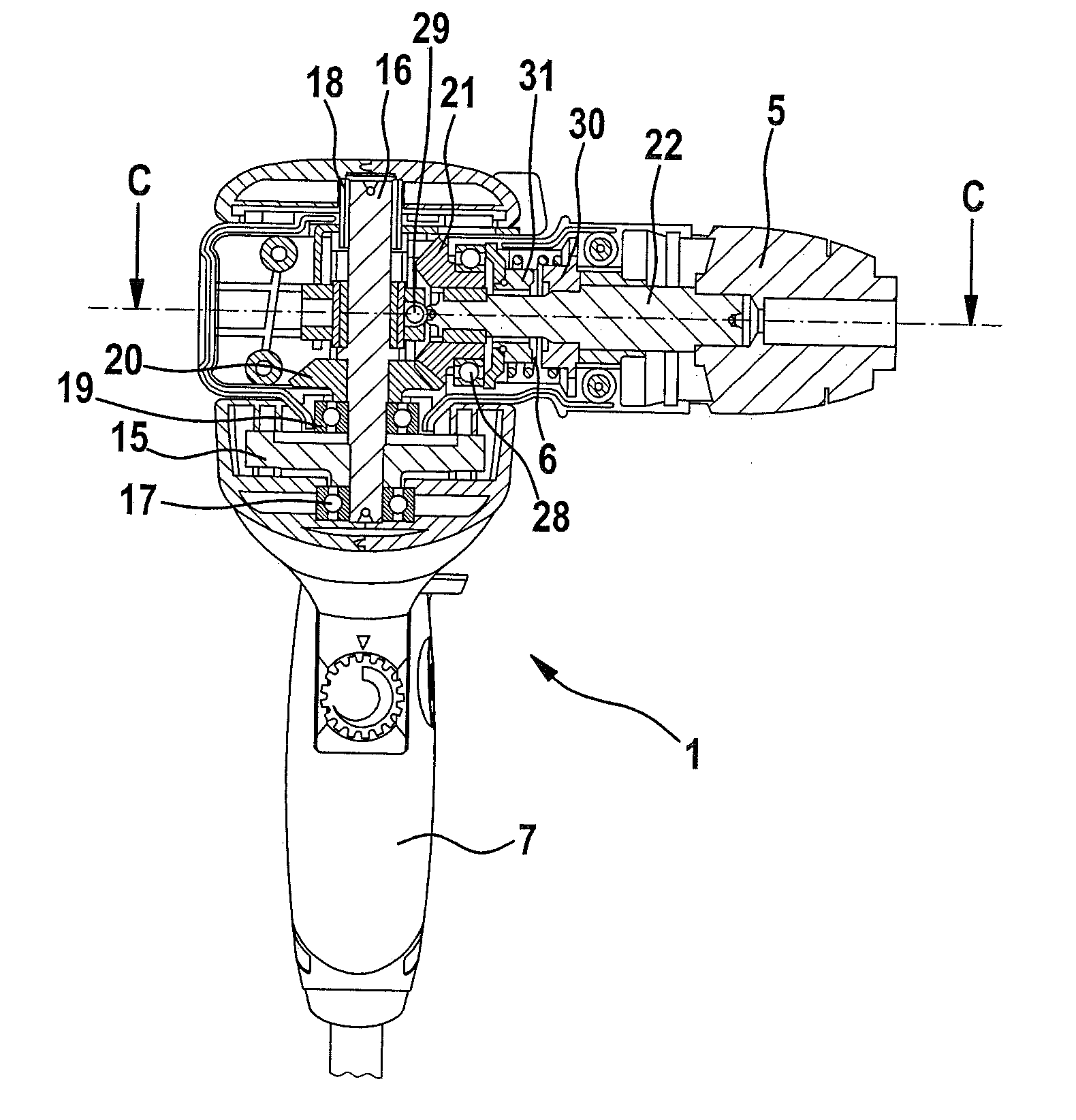
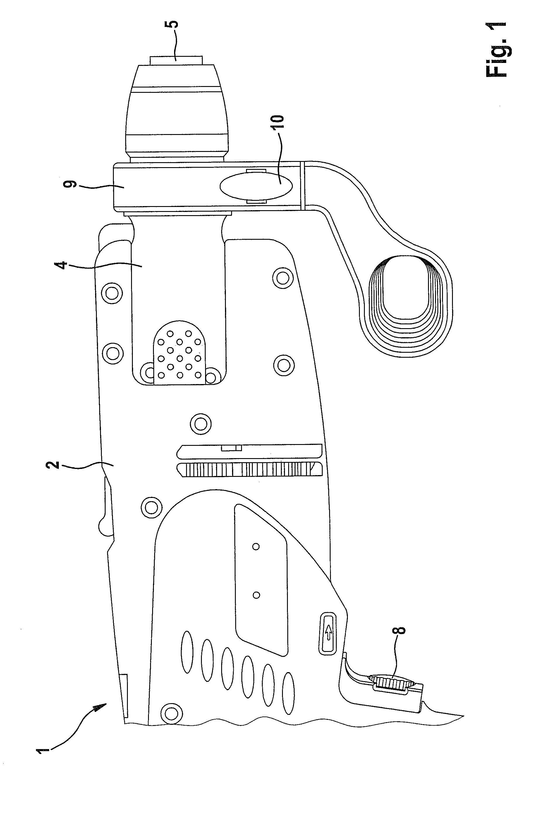
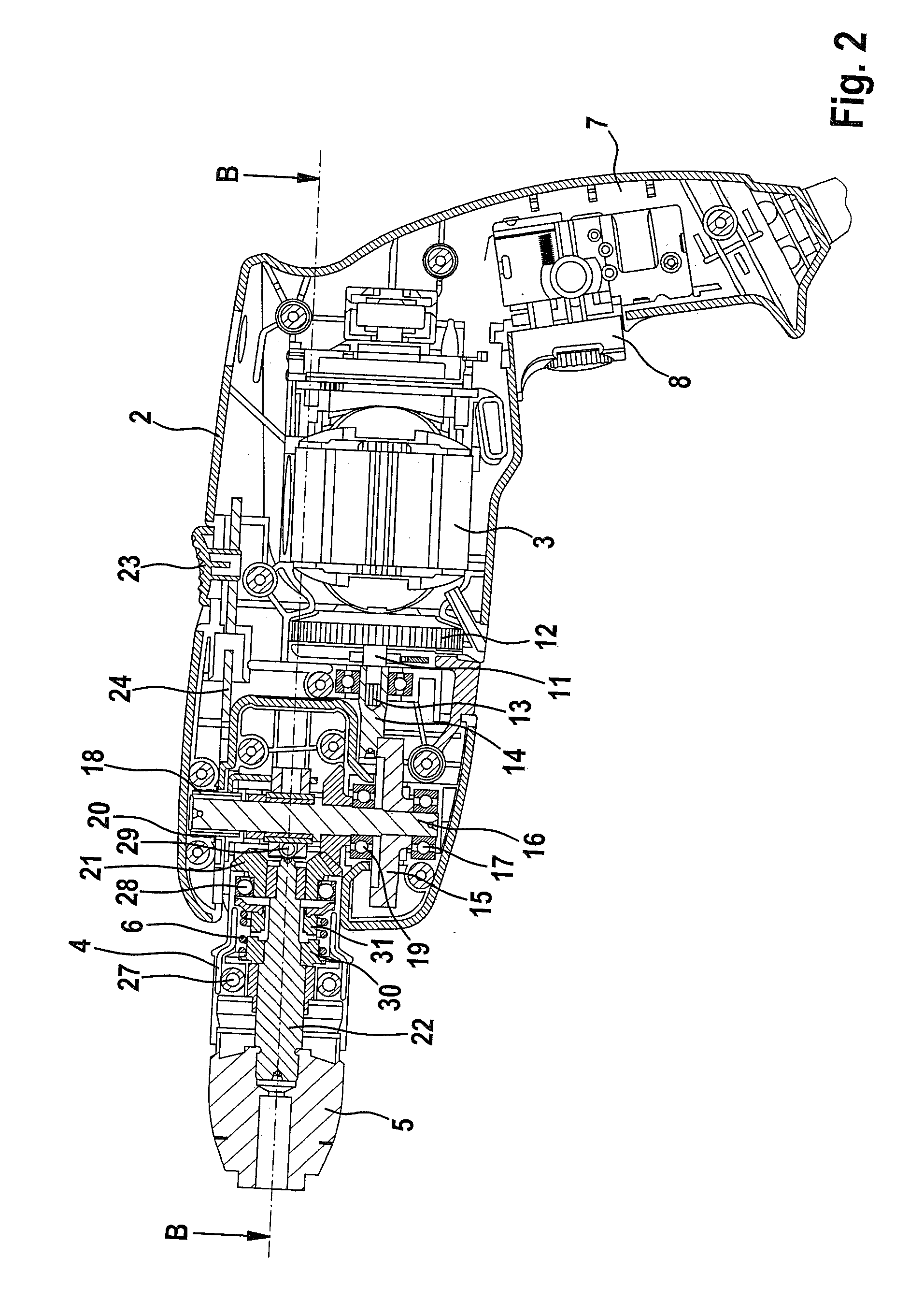
[0027]The figures show an impact drill 1, with a drive motor 3 located in a motor housing 2. Impact drill 1 includes a swivel device 4—which may be swiveled relative to motor housing 2—with a tool fitting 5 and an impact mechanism 6 designed as an index impact mechanism.

[0028]A first handle 7 is provided on motor housing 2, and includes an operating switch 8 for turning drive motor 3—which is designed as a universal motor—on and off. Impact drill 1 also includes a second handle 9, which is detachably connected to swivel device 4. A clamping device with an adjusting screw 10 is provided for securing and releasing second handle 9.

[0029]Swivel device 4 may be adjusted from the straight position shown in FIG. 1 by 90° in any swivel direction 4, thereby resulting in a working range of approximately 180°.

[0030]The motor torque is transferred by motor shaft 11,...


PUM

PropertyMeasurementUnit
angleaaaaaaaaaa
outer diametersaaaaaaaaaa
lengthaaaaaaaaaa

Abstract

An impact drill that includes a drive motor located in a motor housing, an impact mechanism, and a tool fitting. The tool fitting and the impact mechanism are components of a swivel device that is located such that the swivel device may swivel relative to the motor housing.

Description

CROSS-REFERENCE TO A RELATED APPLICATION[0001]The invention described and claimed hereinbelow is also described in German Patent Application DE 10 2006 059 633.1 filed on Dec. 14, 2006. This German Patent Application, whose subject matter is incorporated here by reference, provides the basis for a claim of priority of invention under 35 U.S.C. 119(a)-(d).BACKGROUND OF THE INVENTION[0002]The present invention relates to an impact drill.[0003]Drills without an impact function are known from the related art, which include a pistol handle, central handle or a spade handle and have a short overall length. Devices of this type are of only limited use for working in narrow spaces, however. Angle drills are therefore used for applications of this type. With known angle drills, the motor—which is usually bar-shaped—and the angled head—which is permanently positioned at a 90° angle thereto—enable a compact design to realized and for the reaction torque of the motor to be suitably absorbed.[00...

Claims


Application Information

Patent Timeline
Patent Type & Authority Patents(United States)
IPC IPC(8): B25D15/02
CPCB23B39/14B25D16/00B25F5/02B25D2211/064B25D2250/015B23B45/00B25F5/001
Inventor FUCHS, RUDOLF
Owner ROBERT BOSCH GMBH
Learn More