Apparatus and method for mounting mud flaps on a vehicle

a technology for mounting apparatus and mud flaps, which is applied in the direction of vehicle components, superstructure subunits, transportation and packaging, etc., can solve the problems of failure and detachment of mud flaps, bending or completely ruining the mounting bracket, and tearing a portion or all of the mud flaps from its mounting brack

Inactive Publication Date: 2010-02-02
HAYNES NORMAN ANTHONY
View PDF41 Cites 10 Cited by
  • Summary
  • Abstract
  • Description
  • Claims
  • Application Information

AI Technical Summary

Benefits of technology

[0007]The object of the present invention is to provide an economical and practical means of reducing repair and down-time costs incurred when a mud flap is accidentally pinched between a rotating tire and a curb or other obstruction while backing up the vehicle. By using mud flaps with slit or slotted mounting holes and a spring activated pressure plated to hold the mud flap in their service position, a “weakest link” scenario is created at the mud flap mounting points, producing the desired releaseability function. The same mud flap can then be reinstalled easily in a short length of time on the undamaged mud flap mounting bracket.

Problems solved by technology

Failure and detachment of the mud flap can occur, however, when the vehicle is being backed up and the mud flap becomes pinched between one of the tires and a curb or other obstruction.
The sudden jerk often tears a portion or all of the mud flap from its mounting bracket or bends or completely ruins the mounting bracket.

Method used


Image

  • Apparatus and method for mounting mud flaps on a vehicle
  • Apparatus and method for mounting mud flaps on a vehicle
  • Apparatus and method for mounting mud flaps on a vehicle

Examples


Embodiment Construction

[0024]For the purposes of promoting an understanding of the principles of the invention, reference will now be made to the embodiment illustrated in the drawings and specific language will be used to describe the same. It will nevertheless be understood that no limitation of the scope of the invention is thereby intended, and that any alterations or modifications in the illustrated device, and any further applications of the principles of the invention as illustrated therein are contemplated as would normally occur to one skilled in the art to which the invention relates.

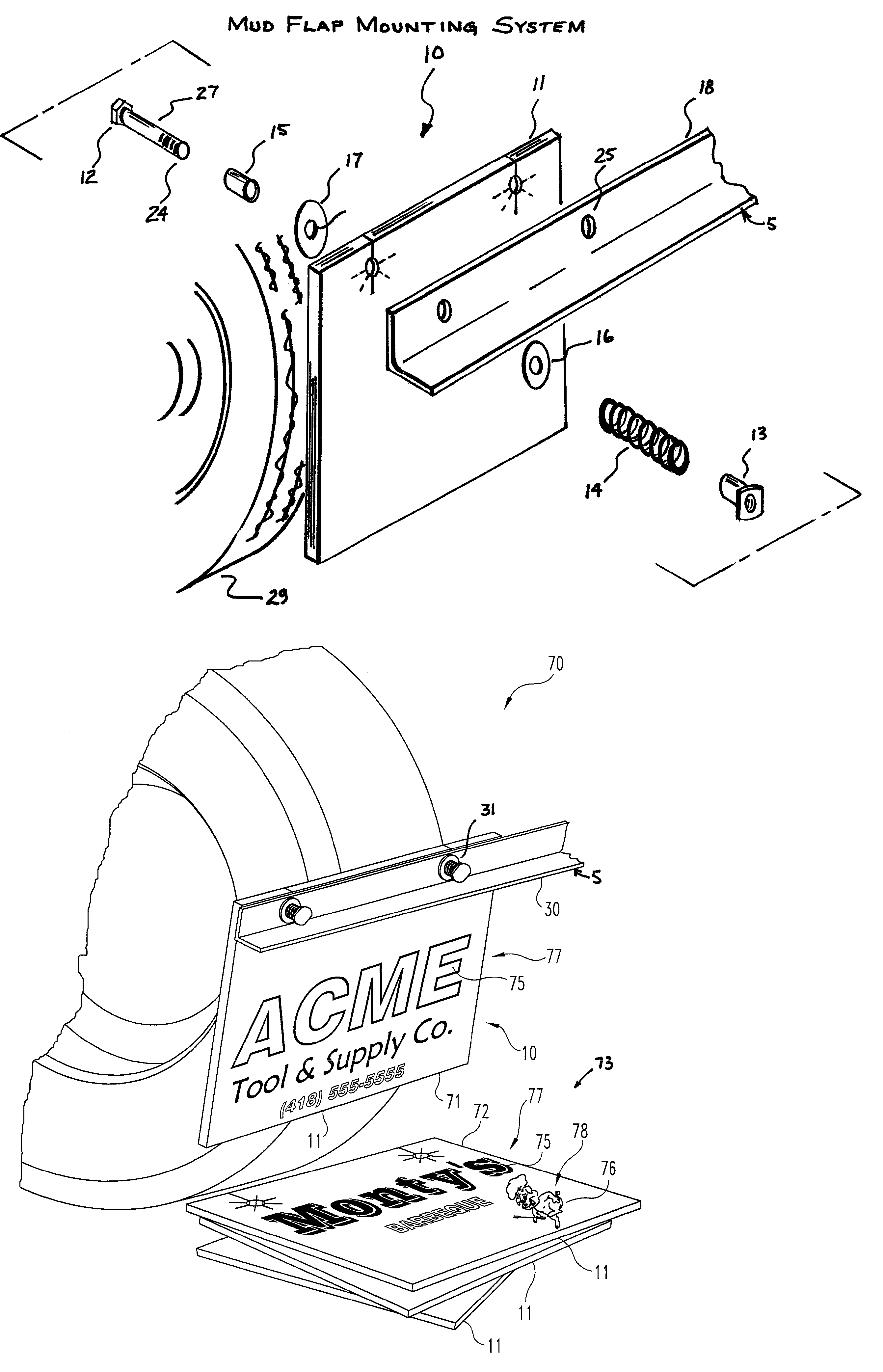
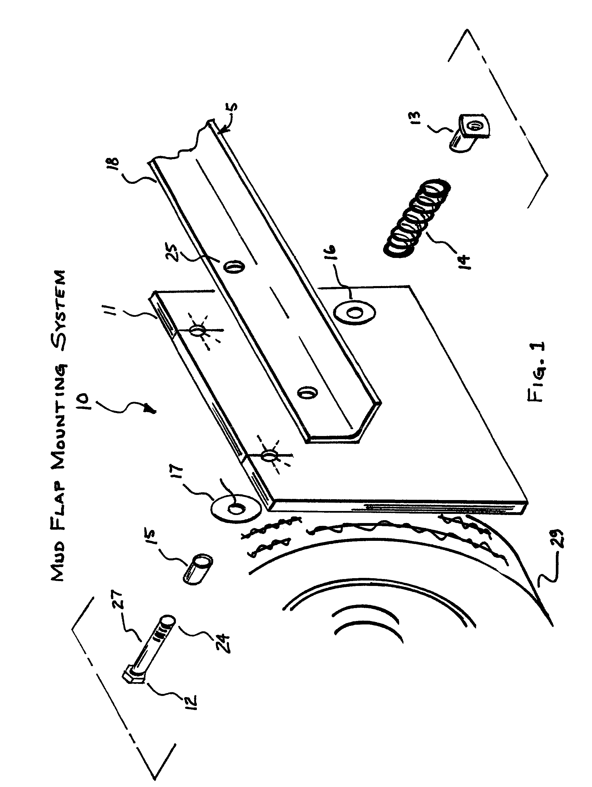
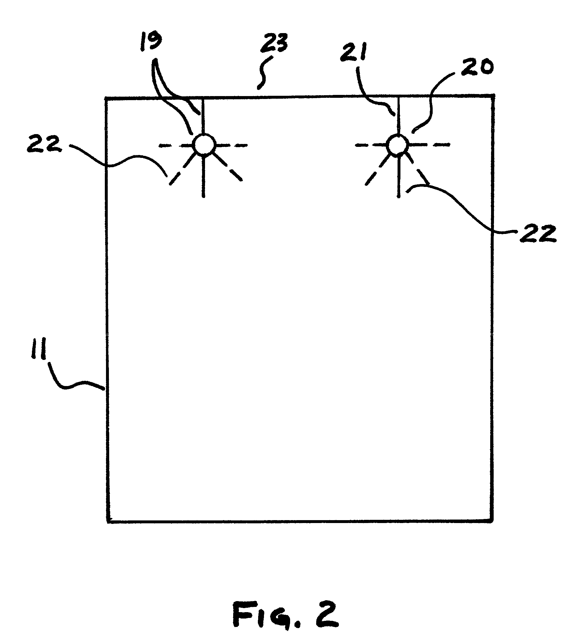
[0025]Referring to FIGS. 1 and 2, there is shown a mud flap mounting system 10 in accordance with one embodiment of the present invention. Mounting system 10 generally includes a mud flap 11, a bolt 12, a tightening member 13, a spring member 14 and a pressure plate 17. Mounting system 10 may also include a spacer 15 and a washer 16. Mounting system 10 is configured to connect with a mounting bracket 18 of a vehicle...


PUM


Abstract

A mud flap mounting system for connecting a mud flap to a mud flap mounting bracket of a vehicle includes a mud flap group and a mud flap mounting assembly for connecting one mud flap of the mud flap group to a vehicle mud flap mounting bracket. The mud flap group includes at least two mud flaps, each comprising a sheet of flexible material having a top edge and defining at least two mounting openings, each mounting opening including a bolt hole, a first slit and at least a second slit, said first slit being a severed portion of the sheet with virtually no loss of material and extending from the top edge to the corresponding bolt hole, and the at least a second slit extending outwardly from the bolt hole. The mud flap mounting assembly includes a pressure plate, a spring member, a bolt with a head and a shank with a distal end, and a tightening member. The shank extends through the pressure plate, mud flap, bracket, and spring member, and the tightening member engages at the distal end of the shank to compress the pressure plate, mud flap, bracket and spring member between the bolt head and the tightening member. Each mud flap of the mud flap group bears at least one of indicia and an image.

Description

REFERENCE TO RELATED APPLICATIONS[0001]This application is a continuation-in-part of U.S. application Ser. No. 10 / 988,063 filed Nov. 13, 2004 now U.S. Pat. No. 7,226,086, which claims priority from U.S. Provisional Applications Nos. 60 / 520,593 filed Nov. 17, 2003 and 60 / 511,385 filed Oct. 15, 2003.FIELD OF THE INVENTION[0002]The present invention relates to the field of vehicle mud flaps and, more particularly, to a method and apparatus for mounting mud flaps on a vehicle such as a truck or semi-tractor / trailer.BACKGROUND OF THE INVENTION[0003]Many jurisdictions require large vehicles such as trucks and semi-tractor / trailers to have mud flaps, which are sheets of flexible material mounted on the vehicle to hang down a short distance behind at least one of the vehicle's wheels. Typically, the mud flap is secured to a mounting bracket, which is secured to the vehicle chassis. Failure and detachment of the mud flap can occur, however, when the vehicle is being backed up and the mud fla...

Claims


Application Information

Patent Timeline
Patent Type & Authority Patents(United States)
IPC IPC(8): B62D25/18
CPCB62D25/188
Inventor HAYNES, NORMAN ANTHONY
Owner HAYNES NORMAN ANTHONY
Why Eureka
Try Eureka