Medical electrical lead

a technology of electrical leads and electrical leads, applied in the field of implantable electrical leads, can solve the problems that the conductors of cardiac pacing leads can sometimes have a tendency to fracture, and achieve the effects of reducing the extensibility of the coiled conductor, reducing the risk of fracture, and increasing the resistance to fractur

Inactive Publication Date: 2010-02-09
MEDTRONIC INC
View PDF17 Cites 26 Cited by
  • Summary
  • Abstract
  • Description
  • Claims
  • Application Information

AI Technical Summary

Benefits of technology

[0005]The present invention is directed toward providing a lead which has an increased resistance to fracture and has the capability of continued function after fracture of a conductor. The lead is provided with a coiled conductor which may be monofilar or multifilar and which extends along the length of the lead, running from an electrical connector at the proximal end of the lead to an electrode at or near the distal end of the lead. In addition, the lead is provided with a stranded conductor which extends along the coiled conductor from a point along the lead body located proximal to the point of expected breakage of the coiled conductor to a point along the lead body located distal to the point of expected breakage. The proximal and distal ends of the stranded conductor in some embodiments are electrically and mechanically coupled to the coiled conductor, limiting the extensibility of the coiled conductor, rendering the coiled conductor less susceptible to axially applied tensile forces and also providing for continued electrical connection to the electrode, in the event that the coiled conductor fractures intermediate the proximal and distal ends of the stranded conductor. In alternative embodiments, the stranded conductor may be coupled only at its proximal or distal end to the coiled conductor or may simply be located in the same lumen of the lead as the coiled conductor, without mechanical connection to the coiled conductor.

Problems solved by technology

The conductors in cardiac pacing leads occasionally have a tendency to fracture due to repetitive application of stress to the conductor.

Method used


Image

  • Medical electrical lead
  • Medical electrical lead
  • Medical electrical lead

Examples


first embodiment

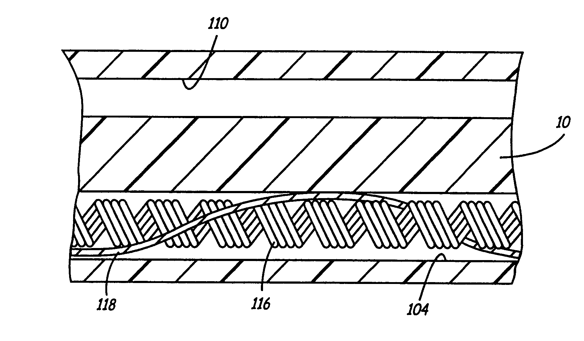
[0033]FIG. 4 is a side, cutaway view through the lead of FIG. 1, illustrating the present invention, also illustrated in FIG. 2. In this view, it can be seen that stranded conductor 118 is loosely spiraled around coiled conductor 116 along the length of the lead, facilitating flexure of the lead body and the conductors located therein. If the ends of conductor 118 are mechanically coupled to conductor 116, this structure also allows for a limited amount of axial elongation of the lead body and conductor 116 along the length of conductor 118. All other labeled elements correspond to those illustrated in FIG. 2.

second embodiment

[0034]FIG. 5 shows a side cutaway view through the lead of FIG. 1, also illustrated in FIG. 3. In this view, the stranded conductor is shown arranged loosely within the lumen of coiled conductor 116. All other labeled elements correspond to those illustrated in FIG. 2.

[0035]In the embodiments illustrated in FIGS. 2, 3, 4 and 5, conductor 118 may be insulated or uninsulated, as discussed above, depending on whether contact between the two conductors along their length is desired. An alternative embodiment in which the stranded conductor is desired to be insulated from the coiled conductor along some portion of its length may employ a separate lumen in the lead body for the stranded conductor, intermediate its points of connection to the coiled conductor. An additional alternative as discussed below may employ a tubular, insulative sheath within or around coiled conductor 116 to insulate it from conductor 118.

[0036]FIG. 6 et seq, shows basic mechanisms which may optionally be employed...

fourth embodiment

[0047]FIG. 11 illustrates a cross section through the invention. All numbered components correspond to identically numbered components in the Figures above. In this embodiment the stranded conductor 118 is located outside of coiled conductor 116 and is insulated from conductor 116 over at least a portion of its length by means of an insulative tube 300, located exterior to conductor 116. Tube 300 may be formed of PTFE or other insulative biocompatible plastic, and may extend over all or some of the length of coiled conductor 116. In this embodiment, it is desirable that the ends of stranded conductor 118 are mechanically coupled to the coiled conductor 116 on either side of the tube 300.

[0048]FIG. 12 illustrates a side, cut-away view through the fourth embodiment of the invention as illustrated in FIG. 11. All numbered components correspond to identically numbered components in the Figures above


PUM


Abstract

An implantable lead which has an increased resistance to fracture and has the capability of continued function after fracture of a conductor. The lead is provided with a coiled conductor which may be monofilar or multifilar and which extends along the length of the lead, running from an electrical connector at the proximal end of the lead to an electrode at or near the distal end of the lead. In addition, the lead is provided with a stranded conductor which is electrically coupled to the coiled conductor at point along the lead body located proximal to the point of expected breakage of the coiled conductor and at a point along the lead body located distal to the point of expected breakage. The proximal and distal ends of the stranded conductor in some embodiments are also mechanically coupled to the coiled conductor.

Description

[0001]This application is a continuation of prior application Ser. No. 09 / 482,775 filed Jan. 13, 2000, now U.S. Pat. No. 6,119,042 which is a divisional application of Ser. No. 09 / 247,324, Feb. 10, 1999, now U.S. Pat. No. 6,061,598 granted May 9, 2000, which is a divisional of Ser. No. 09 / 070,171, Apr. 30, 1998, now U.S. Pat. No. 6,018,683 granted Jan. 25, 2000, which is a divisional application of application Ser. No. 08 / 843,763 filed Apr. 21, 1997.[0002]This application claims the benefit of provisional application 60 / 033,511 filed Dec. 19, 1996.BACKGROUND OF THE INVENTION[0003]The present invention relates to implantable electrical leads generally, and more specifically to cardiac pacing leads.[0004]The conductors in cardiac pacing leads occasionally have a tendency to fracture due to repetitive application of stress to the conductor. One way in which this problem has previously been addressed is by reinforcing the lead body in the area in which stress is to be expected, as in U....

Claims


Application Information

Patent Timeline
Patent Type & Authority Patents(United States)
IPC IPC(8): A61N1/00A61N1/05
CPCA61N1/056A61N1/0568A61N1/0573A61N2001/058A61N1/0563
Inventor VERNESS, DAVID D.HUEPENBECKER, GEORGE M.WAHLSTROM, DALE A.
Owner MEDTRONIC INC
Why Eureka
Try Eureka