Self-righting pool cleaning robot

a self-righting, pool technology, applied in the direction of underwater equipment, vessel safety, floating buildings, etc., can solve the problem that similar problems may arise in the motion of submerged vehicles of other types

Inactive Publication Date: 2010-02-16
AQUATRON ROBOTIC SYST
View PDF8 Cites 33 Cited by
  • Summary
  • Abstract
  • Description
  • Claims
  • Application Information

AI Technical Summary

Benefits of technology

[0005]Embodiments of the present invention that are described hereinbelow provide a novel mechanism and method for ensuring that a submerged vehicle maintains the proper attitude relative to the surface along which the vehicle is traveling. In some embodiments, the vehicle comprises a hollow tube, which is filled with fluid. The tube contains one or more objects that have a specific gravity less than that of the fluid and are capable of moving within the tube. Changes in the attitude of the vehicle cause the objects to shift in the tube, thereby shifting the center of buoyancy of the vehicle in a manner that ensures that the vehicle maintains contact with the surface and does not tip over regardless of the angle of the surface.
[0017]inserting in the hollow tube one or more objects, which have a second specific gravity that is less than the first specific gravity, so that the one or more objects are capable of moving inside the hollow tube so as to stabilize the housing in response to changes of an angle of an interior surface of a container in which the vehicle is submerged as the vehicle travels over the interior surface.

Problems solved by technology

Similar problems may arise in motion of submersible vehicles of other types.

Method used


Image

  • Self-righting pool cleaning robot
  • Self-righting pool cleaning robot
  • Self-righting pool cleaning robot

Examples


Embodiment Construction

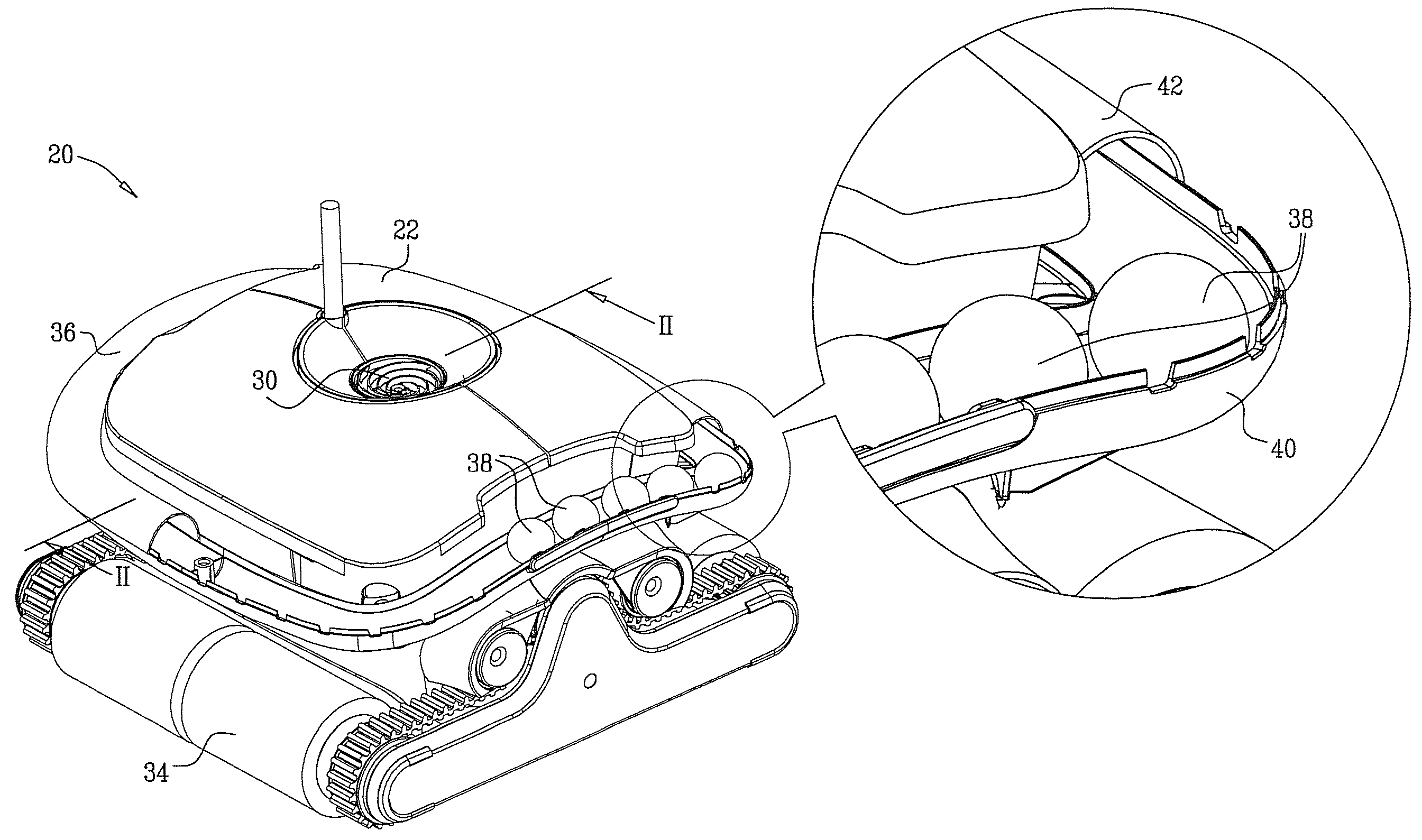
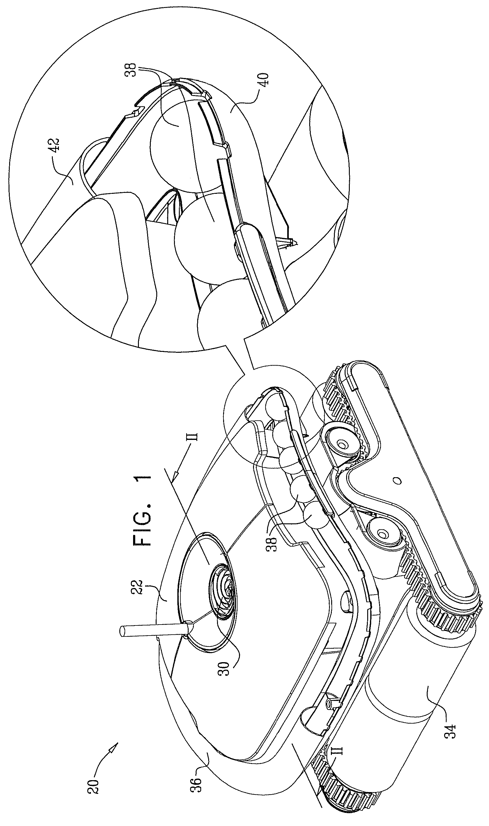
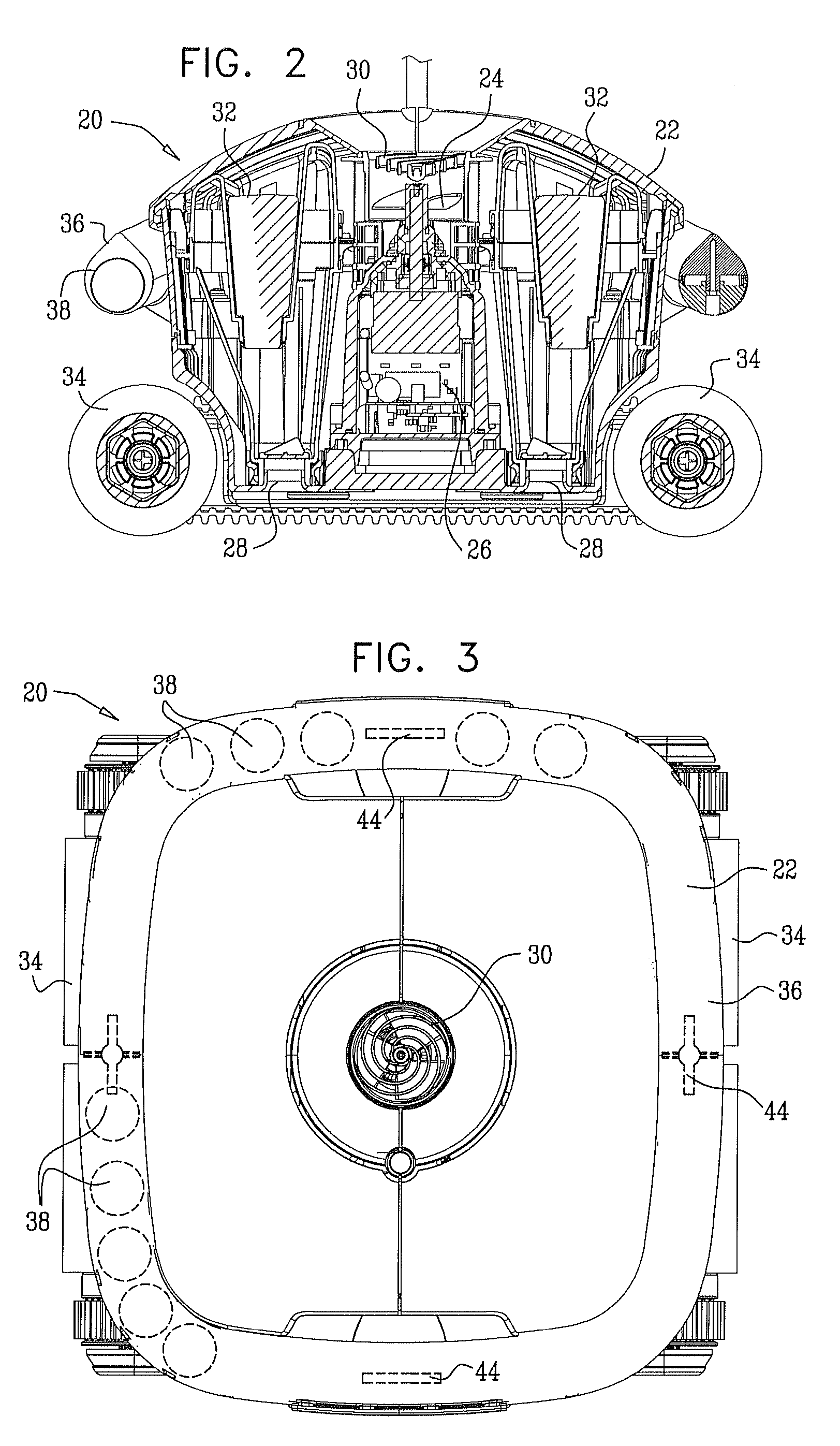
[0023]Reference is now made to FIGS. 1-3, which schematically illustrate a robot 20, which is a submersible vehicle for cleaning the interior of a swimming pool or other fluid container, in accordance with an embodiment of the present invention. FIG. 1 is a schematic, pictorial, partly cutaway view of the robot. FIG. 2 is a sectional view, taken along a line II-II in FIG. 1. FIG. 3 is a top view.

[0024]Robot 20 comprises a housing 22, which contains an impeller 24 driven by a motor 26. The impeller draws water into housing 22 through ingress ports 28 on the lower side of the housing, which is normally adjacent to the surface being cleaned. The water passes from the ingress ports into filters 32 inside the housing, and then out through an egress port 30 on the upper side of the robot. Contaminants in the water are thus trapped inside the filters. The filters comprise a suitable, flexible filter material, such as a dense-weave cloth or porous synthetic.

[0025]A propulsion motor (not sho...


PUM


Abstract

A vehicle includes a submersible housing and a propulsion mechanism, which is coupled to drive the housing over an interior surface of a container in which the housing is submerged. A hollow tube is fixed to the housing and is configured to be filled with a fluid having a first specific gravity. One or more objects, which have a second specific gravity that is less than the first specific gravity, are contained within and capable of moving inside the hollow tube so as to stabilize the housing in response to changes of an angle of the interior surface over which the vehicle travels.

Description

CROSS-REFERENCE TO RELATED APPLICATION[0001]This application claims the benefit of U.S. Provisional Patent Application 60 / 857,733, filed Nov. 7, 2006.FIELD OF THE INVENTION[0002]The present invention relates generally to underwater cleaning devices, and specifically to devices for cleaning the inner surfaces of a swimming pool or other liquid container.BACKGROUND OF THE INVENTION[0003]A variety of submersible devices are known in the art for automated cleaning of swimming pools. Some of these devices comprise wheels or treads with an internal propulsion system, so that the device travels autonomously along the floor (and sometimes the walls) of the swimming pool. Devices of this sort are referred to commonly as “robots.” While the robot travels through pool, it sucks contaminants from the floor (and walls) through ports in the lower surface of the robot into an internal filter element.SUMMARY OF THE INVENTION[0004]The inner surfaces of swimming pools and other liquid containers are ...

Claims


Application Information

Patent Timeline
Patent Type & Authority Patents(United States)
IPC IPC(8): B63B59/00
CPCE04H4/1654
Inventor GORELIK, BORISSHPITZER, TZACHIYAKOBOVITCH, AMIR
Owner AQUATRON ROBOTIC SYST
Why Eureka
Try Eureka