Device and method for detecting deformation of the viscoelastic magnet

a viscoelastic magnet and deformation technology, applied in the direction of instruments, apparatus for force/torque/work measurement, measurement of tension, etc., can solve the problems of complex structure, high cost, and difficulty in detecting deformation of viscoelastic magnets, and achieve the effect of accurate gripping and manipulating an arbitrary object and higher-affinity physical interaction

Active Publication Date: 2010-02-16
SONY CORP
View PDF5 Cites 21 Cited by
  • Summary
  • Abstract
  • Description
  • Claims
  • Application Information

AI Technical Summary

Benefits of technology

[0016]Therefore, it is desirable to make it possible to easily detect a static state and a dynamic state of an object that is in contact with a robot hand or a manipulator or physical interaction of the robot hand or the manipulator with a human.
[0035]According to the embodiments of the present invention, it is possible to accurately grip and manipulate an arbitrary object using a robot hand or a manipulator and perform higher-affinity physical interaction of the robot hand or the manipulator with a human.

Problems solved by technology

However, there are only a few tactile sensors that make it possible to grip and manipulate an arbitrary object using a robot hand or a manipulator and perform high-affinity physical interaction of the robot hand or the manipulator with a human.
However, the tactile sensors often have various problems and complicated structures and are expensive.

Method used


Image

  • Device and method for detecting deformation of the viscoelastic magnet
  • Device and method for detecting deformation of the viscoelastic magnet
  • Device and method for detecting deformation of the viscoelastic magnet

Examples


Embodiment Construction

[0067]Embodiments of the present invention will be hereinafter explained. A correspondence relation between elements of the present invention and the embodiments described or shown in the specification or the drawings is described as follows. This description is a description for confirming that the embodiments supporting the present invention are described or shown in the specification or the drawings. Therefore, even if there is an embodiment that is described or shown in the specification or the drawings but is not described herein as an embodiment corresponding to an element of the present invention, this does not mean that the embodiment does not correspond to the element. Conversely, even if an embodiment is described herein as an embodiment corresponding to an element of the present invention, this does not mean that the embodiment does not correspond to elements other than the element.

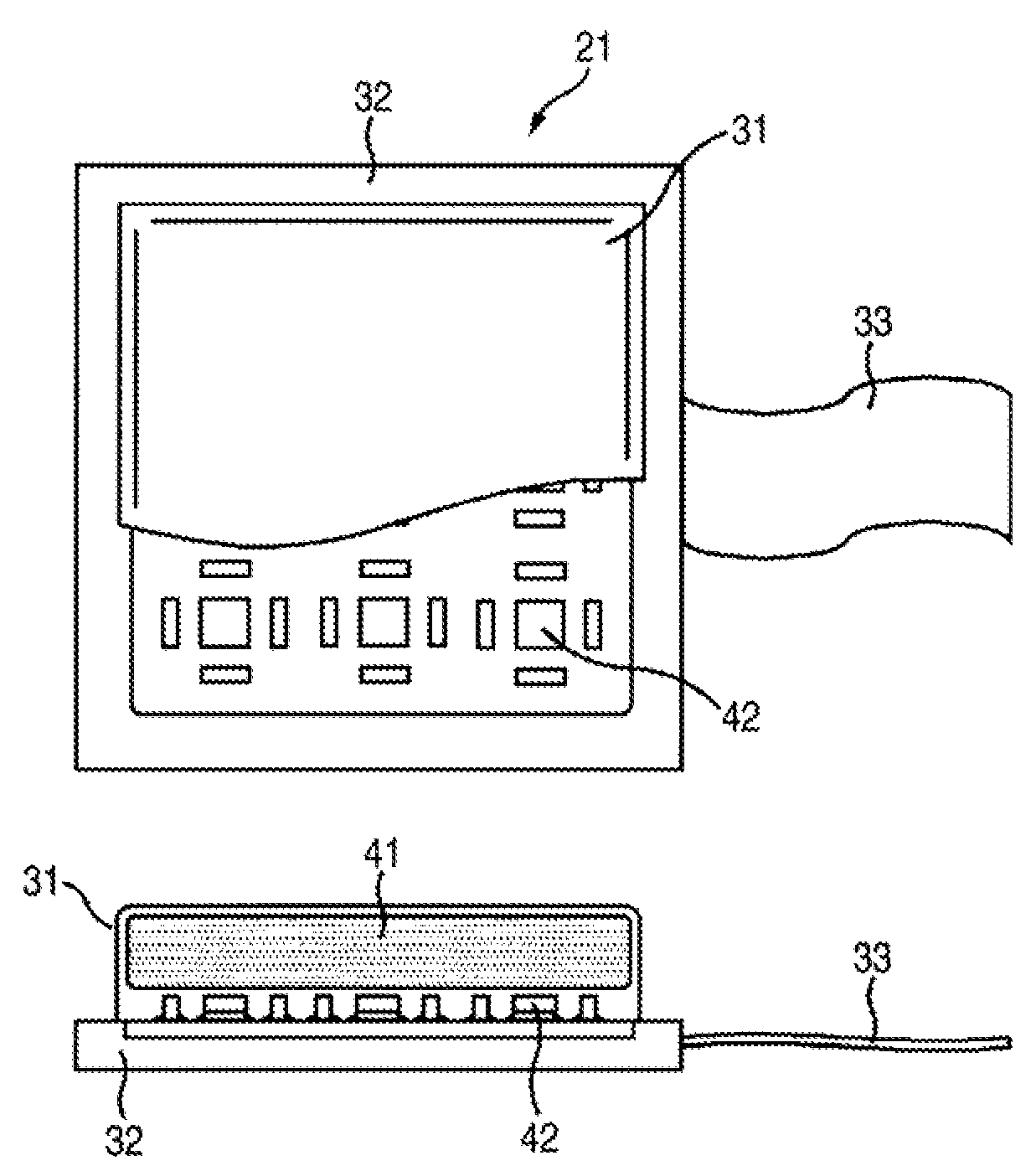
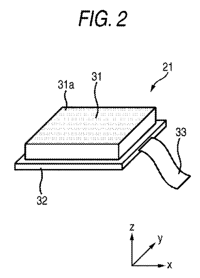
[0068]A detecting device (e.g., a sensor 21 in FIG. 3) according to an embodiment of the pr...


PUM


Abstract

A detecting device includes a viscoelastic magnet obtained by kneading and molding a magnet material and a viscoelastic material and a magnetic-flux detecting unit that detects a change in a magnetic flux density vector due to deformation of the viscoelastic magnet.

Description

CROSS-REFERENCES TO RELATED APPLICATIONS[0001]The present invention contains subject matter related to Japanese Patent Application JP 2006-216475 filed in the Japanese Patent Office on Aug. 9, 2006, the entire contents of which being incorporated herein by reference.BACKGROUND OF THE INVENTION[0002]1. Field of the Invention[0003]The present invention relates to a detecting device and a detecting method, and, more particularly to a detecting device and a detecting method adapted to be capable of easily detecting a static state and a dynamic behavior of an object that is in contact with a robot hand or a manipulator or physical interaction of the robot hand or the manipulator with a human.[0004]2. Description of the Related Art[0005]In order to dexterously grip and manipulate arbitrary objects having various sizes, shapes, surface states, and weights using a robot hand or a manipulator and perform high-affinity physical interaction of the robot hand or the manipulator with a human, it...

Claims


Application Information

Patent Timeline
Patent Type & Authority Patents(United States)
IPC IPC(8): G01R33/02
CPCG01R33/04G01R33/07
Inventor KISHIDA, TAKEOTSUBOI, TOSHIMITSUFUKUSHIMA, TETSUHARUYABANA, TAKAFUMI
Owner SONY CORP
Why Eureka
Try Eureka