Pneumatic tire

a technology of pneumatic tires and tires, applied in the field of pneumatic tires, can solve the problems of greatly affecting the durability of a region of display parts, and achieve the effect of improving durability

Inactive Publication Date: 2010-02-23
BRIDGESTONE CORP
View PDF20 Cites 8 Cited by
  • Summary
  • Abstract
  • Description
  • Claims
  • Application Information

AI Technical Summary

Benefits of technology

[0010]This invention has an object to provide a pneumatic tire achieving an improvement of durability in a manner that a rigidity difference is made not to occur between a decorative portion and a display portion.
[0012]The rigidity difference is resolved, and thus the occurrence of the stress concentration is decreased, and it is made possible to restrict the crack caused by the flex fatigue for a long period of time without damaging the exterior appearance. As a result of this, the durability of the region of the protruding portions is improved to a great extent.
[0014]In such a way, even if pluralities of the bottoms and tops continue between the protruding portion and the protruding portion, a large rigidity difference does not occur owing to the high decorative portion, and the flex fatigue can be restricted from occurring concentratedly on one part. Therefore, the occurrence of the crack can be securely restricted for a long period of time without damaging the exterior appearance.
[0016]In such a way, corner portions where the stress concentration is prone to occur are removed, and thus the occurrence of the crack caused by the flex fatigue can be securely restricted.
[0019]Moreover, a corner region connecting the decorative portion and each protruding portion may be formed of a round portion. This is because the crack can be prevented from occurring, which may be caused by a concentration of the flex fatigue on one part.

Problems solved by technology

When the stress concentration occurs repeatedly in the root groove 107, such an occurrence is prone to lead to a crack due to flex fatigue of the root groove 107, causing a problem that durability of a region of the display portions is greatly affected.

Method used


Image

  • Pneumatic tire
  • Pneumatic tire
  • Pneumatic tire

Examples


first embodiment

[0033]this invention will be concretely described below while referring to FIG. 3 to FIG. 5.

[0034]FIG. 5 shows a schematic cross-sectional view of a pneumatic safety tire 1. The pneumatic safety tire 1 includes sidewalls 5 continuous from both ends constituting a cylindrical crown portion 3 toward an inside in a diameter direction, bead portions 9 in which bead rings 7 are embedded in tip portions, a carcass layer 11 disposed from one of the sidewalls 5 through the crown portion 3 to the other sidewall (not shown), both ends of the carcass layer 11 being wound around and fixed to the bead rings 7, and a belt layer 13 made of a plurality of unstretchable belts arranged over a region of the crown portion 3 and stacked on the carcass layer 11.

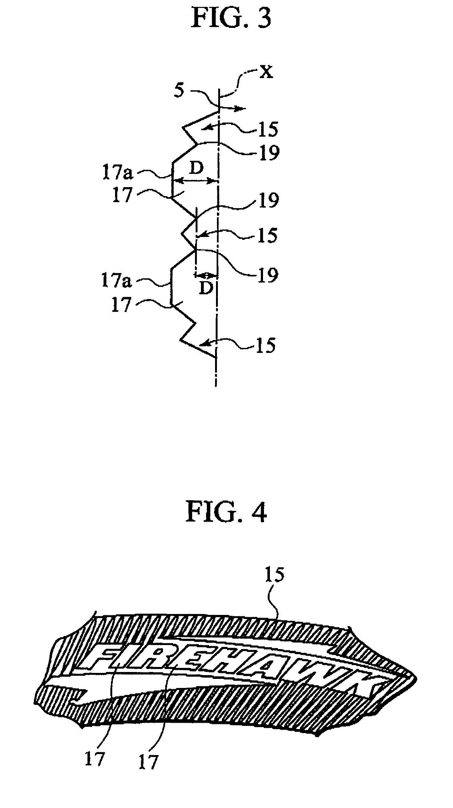
[0035]Meanwhile, on the sidewall 5, a continuous decorative portion 15 in which serrations are cut such that cross-sectional tops and bottoms continue with each other as shown in FIG. 4 is arranged in a ring shape in a state of being tilted to som...

second embodiment

[0043]FIG. 7 is one showing the joined portion.

[0044]Specifically, in this embodiment, the joined portions of the decorative portion 15 and display portion 17 and of the display portion 17 and display portion 17 are formed into a shape integrally continuous in flat portions 21 higher than the bottoms of the decorative portion 15.

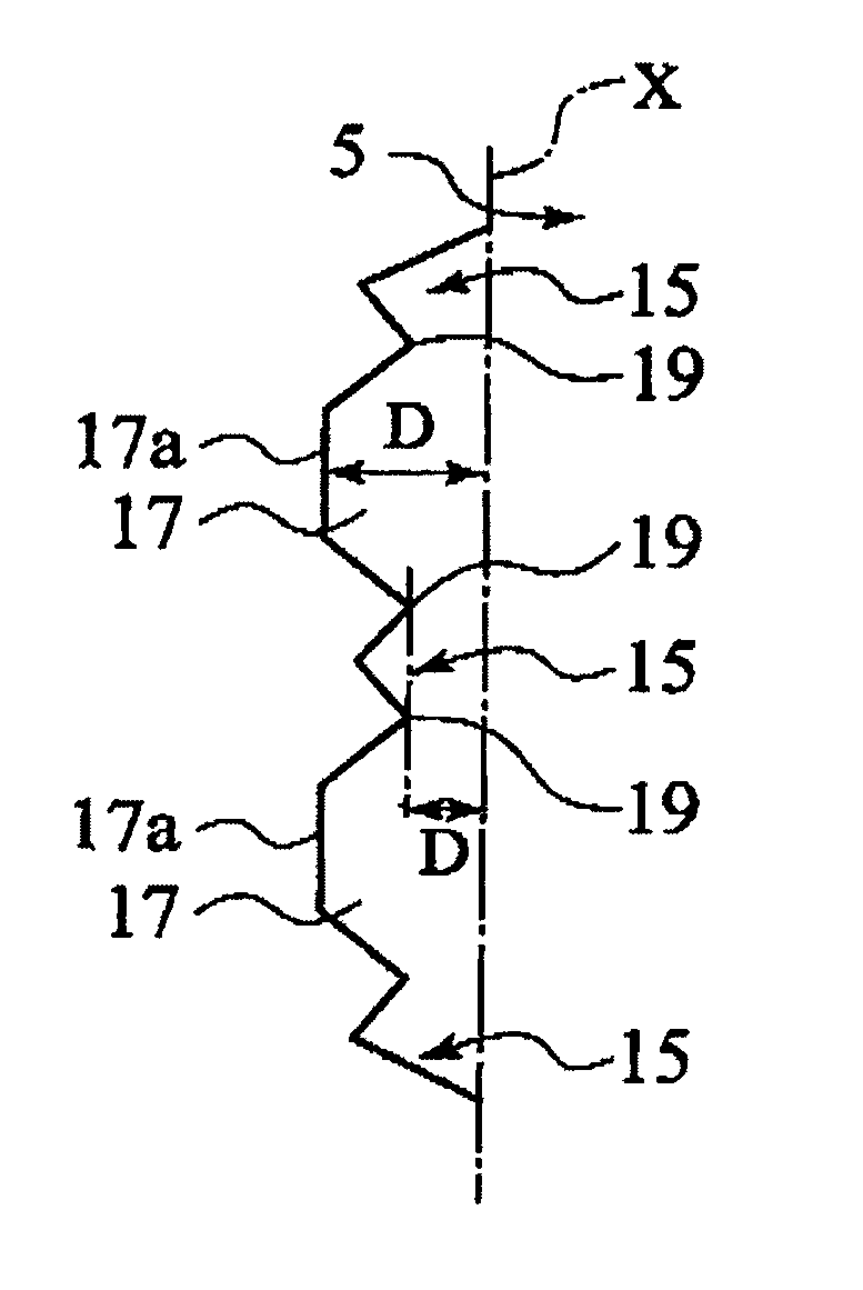
[0045]In the flat portions 21, a ratio of a height DB from a root groove line X connecting a root groove and root groove (two-dotted lines) of the decorative portion 15 is set at 30% to 70%, and preferably, 50% to 70% with respect to a height DA to the top surfaces 17a of the display portions 17. As the height DB of the flat portions 21 becomes higher, a difference of elevation between the flat portions 21 and the top surfaces 17a is decreased, and thus it becomes difficult to recognize the outer circumferential edge lines of the display portions 17.

[0046]As a result of this, the display function as display portions is lowered. Accordingly, from a viewpoint ...

third embodiment

[0049]Next, the present invention will be described by use of FIG. 8 to FIG. 10.

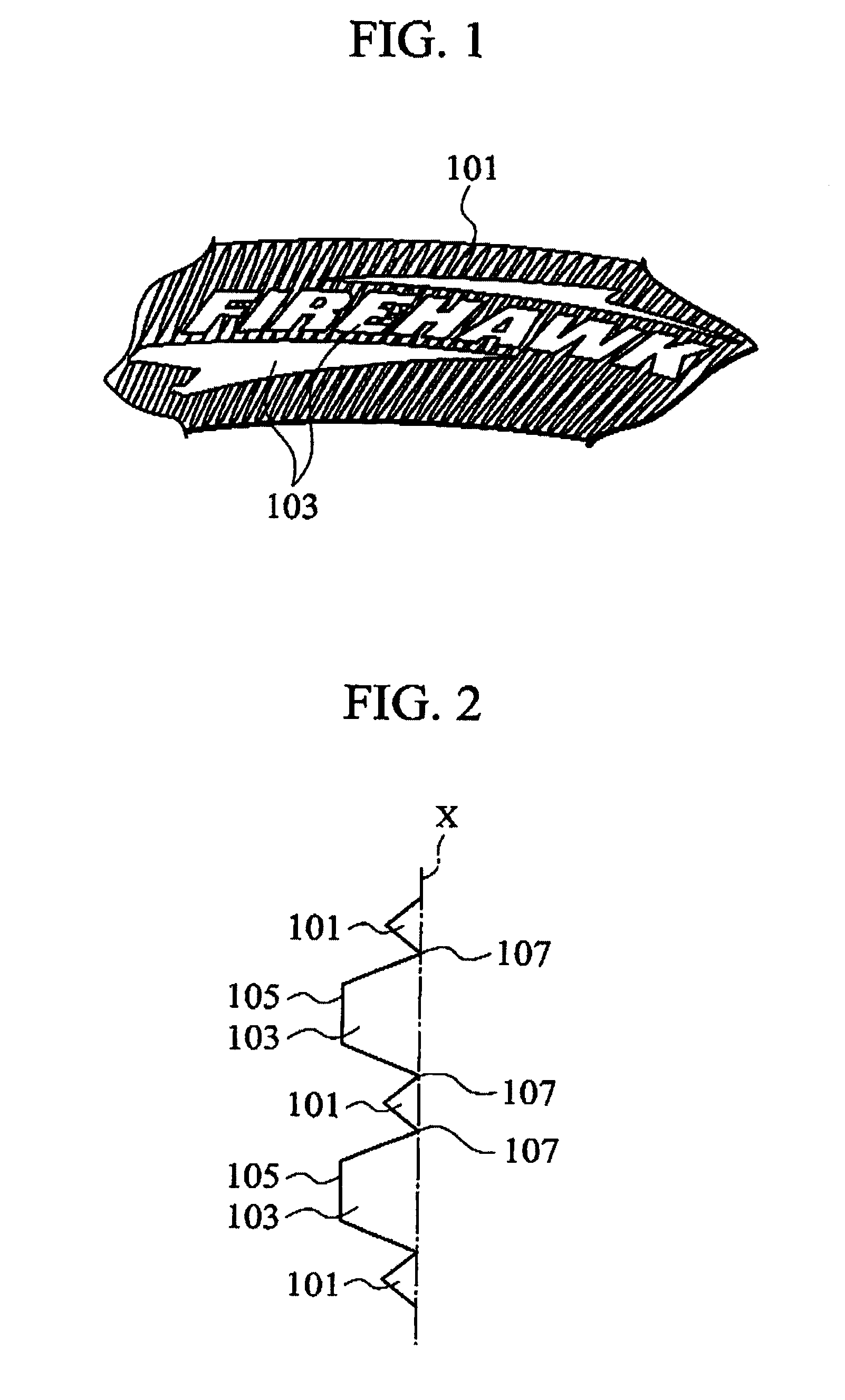
[0050]FIG. 8 shows a case where display portions 103 are directly adjacent to each other without interposing a decorative portion 101 therebetween in Conventional example. A V-shaped root groove 109 is formed between the display portions 103. A height of this root groove 109 becomes the same as that of a root groove line X connecting the display portions 103 and the decorative portion 101. Therefore, the stress concentration becomes prone to occur in the root groove 109.

[0051]In the third embodiment of the present invention, as shown in FIG. 9, the display portions 17 are directly adjacent to each other without interposing the decorative portion 15 therebetween. A bottom 23 of the joined portion of the display portions 17 and the bottoms 19 of the joined portions of the display portions 17 and the decorative portion 15 are set at positions higher than the bottoms of the decorative portion 15 and formed i...


PUM


Abstract

On a region of a ring-shaped continuous decorative portion 15 formed of tops and bottoms in cross-section, protruding portions 17 higher than the decorative portion 15 and having a predetermined surface area are provided. A joined portion of the decorative portion 15 and each protruding portion 17 or of the protruding portions is set higher than the bottoms of the decorative portion 15, and a rigidity difference between the protruding portions 17 and the decorative portion 15 is resolved, thus restricting an occurrence of a stress concentration.

Description

TECHNICAL FIELD[0001]This invention relates to a pneumatic tire contributing to durability of a region of a display portion provided on a sidewall.BACKGROUND ART[0002]In general, on a sidewall of a pneumatic tire, a variety of characters, numbers and graphics (hereinafter, referred to as a display portion) are provided in order to meet legal criteria of the respective countries around the world.[0003]When the display portion is provided, from a viewpoint of improving an exterior appearance of the product, for example, as shown in FIG. 1, display portions 103 are sometimes provided on an area of a decorative portion 101 in which ring-shaped longitudinal ridges having cross sections composed of crests and roots are applied, that is, so-called serrations are cut.[0004]The display portions 103 are higher than the decorative portion 101 and have a shape in which each upper surface 105 has a large surface area when being enlarged as shown in FIG. 2.[0005]As apparent from FIG. 2, rigidity ...

Claims


Application Information

Patent Timeline
Patent Type & Authority Patents(United States)
IPC IPC(8): B60C13/02B60C13/00
CPCB60C13/001B60C13/02
Inventor SANO, MASAHIRO
Owner BRIDGESTONE CORP
Why Eureka
Try Eureka