Direct coupled wide-bandwidth front-end with smart bias control amplifier

a wide-bandwidth, bias control technology, applied in the field of data storage devices, can solve the problems of low phase distortion and transient recovery, and achieve the effects of low electronic noise, fast transient recovery, and high bandwidth

Inactive Publication Date: 2010-02-23
WESTERN DIGITAL TECH INC
View PDF24 Cites 6 Cited by
  • Summary
  • Abstract
  • Description
  • Claims
  • Application Information

AI Technical Summary

Benefits of technology

[0017]Embodiments of the present invention provide a mixed-mode amplifier for amplifying signals in data storage devices such as disk drives. The amplifier architecture is called a direct-coupled wide-bandwidth front-end with smart-bias control (DCSB) amplifier. The DCSB amplifier has the following advantageous characteristics: low electronic noise; high bandwidth (fc≈eclk×0.5, where fclk is the data clock frequency); low phase distortion by having a single-pole high-pass frequency response; fast transient recovery; and low corner frequency (fl≈fc / K=fclk / (2 IK)), where the proportional factor K=200 to 1000 (for perpendicular recording). Low electronic noise and high bandwidth are typical requirements for a front-end amplifier used in a disk drive system and can marginally be achieved with conventional amplifiers, but low phase distortion, fast transient recovery, and a good low-corner frequency performance are only possible with a DCSB amplifier. The above requirements become even more stringent with perpendicular recording (PR). The smart bias control is attained by a self training mix-mode circuit that enables a DCSB amplifier to remember its DC operating point. With the DCSB amplifier remembering its DC operating point, the amplifier can recover very quickly from an “off” or “standby” state and has an improved frequency-response performance (low phase distortion and low corner frequency).

Problems solved by technology

Low electronic noise and high bandwidth are typical requirements for a front-end amplifier used in a disk drive system and can marginally be achieved with conventional amplifiers, but low phase distortion, fast transient recovery, and a good low-corner frequency performance are only possible with a DCSB amplifier.

Method used


Image

  • Direct coupled wide-bandwidth front-end with smart bias control amplifier
  • Direct coupled wide-bandwidth front-end with smart bias control amplifier
  • Direct coupled wide-bandwidth front-end with smart bias control amplifier

Examples


Embodiment Construction

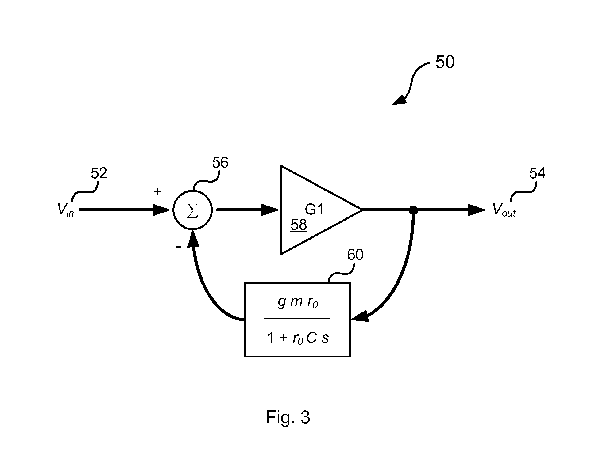
[0041]One aspect of the DCBS amplifier architecture relates to the feedback requirement to remove the DC bias. As mentioned earlier, the front-end amplifier only amplifies the read-back signal and the feedback is used to suppress the amplification of the DC bias voltage applied to the read sensor. FIG. 3 shows a representation of a first order feedback system 50. The voltage input 52 is fed into a summing junction 56, which is then sent to amplifier 58 input. The output of the amplifier 58 goes to the voltage output 54, and also to feedback block 60. The output of the feedback block 60 is then subtracted from the voltage input 52, thus creating the feedback signal. This feedback has a frequency roll-off set by resistance value r0 and capacitor value C in the feedback block 60, and the forward gain is set by the gain value G1 as determined by the amplifier 58. In addition, the feedback gain is set by the transconductance value gm, so the loop gain is then G1gm. The equivalent equatio...


PUM

PropertyMeasurementUnit
bias voltageaaaaaaaaaa
output voltageaaaaaaaaaa
bias voltageaaaaaaaaaa

Abstract

Embodiments of the present invention provide a mixed-mode amplifier for amplifying signals in data storage devices such as disk drives. In one embodiments, a circuit for amplifying data signals comprises a magnetoresistive sensor having a bias voltage applied thereto; a signal amplifier which amplifies a signal detected by the magnetoresistive sensor having the bias voltage applied thereto; a feedback control block which is coupled to an output of the signal amplifier and outputs a feedback current used to vary a loop gain of the circuit; a bias setting circuit which outputs a bias setting current; and a transimpedance amplifier which receives the bias setting current from the bias setting block and the feedback current from the feedback control block and generates the bias voltage applied to the magnetoresistive sensor.

Description

BACKGROUND OF THE INVENTION[0001]The present invention relates to data storage devices including hard disk drives, and more particularly to amplifying data signals in such devices.[0002]A hard disk drive is one of the most widely used external storage devices for a computer. A magnetic disk or plurality of magnetic disks are typically used as a storage medium for the hard disk drive, which uses sectors as minimum data recording units. The sectors are obtained by radially dividing tracks that are obtained by concentrically dividing the disk surface. The hard disk drive has a composite magnetic head (read / write head) which comprises two devices: a read sensor and a write element. The read sensor reads data stored on the magnetic disk, whereas the write element writes data onto the magnetic disk. The magnetic head is mounted on an actuator mechanism, which is moved by a VCM (voice coil motor).[0003]The read sensors used for reading data from the magnetic disks typically comprise magnet...

Claims


Application Information

Patent Timeline
Patent Type & Authority Patents(United States)
IPC IPC(8): G11B5/03
CPCG11B5/02G11B2005/0018
Inventor CONTRERAS, JOHNKLAASSEN, KLAAS
Owner WESTERN DIGITAL TECH INC
Why Eureka
Try Eureka