Rodent bait station

Active Publication Date: 2010-03-02
FRISCH STEVEN
View PDF160 Cites 25 Cited by
  • Summary
  • Abstract
  • Description
  • Claims
  • Application Information

AI Technical Summary

Benefits of technology

[0011]It is an object of the present invention to provide a rodent bai

Problems solved by technology

U.S. Pat. No. 4,658,536 to Baker for a Bait Station, shows a device with the overall configuration of a capital letter H. Openings are provided at the ends of the arms of the H and bai

Method used


Image

  • Rodent bait station
  • Rodent bait station
  • Rodent bait station

Examples


Embodiment Construction

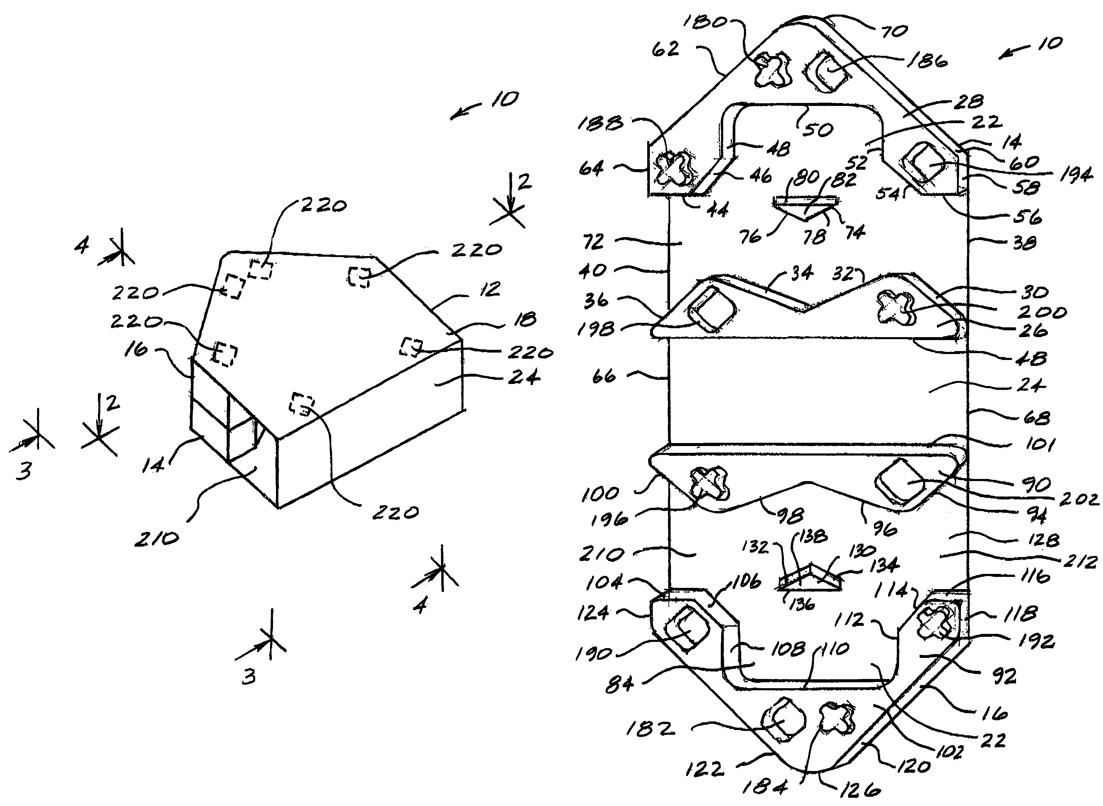
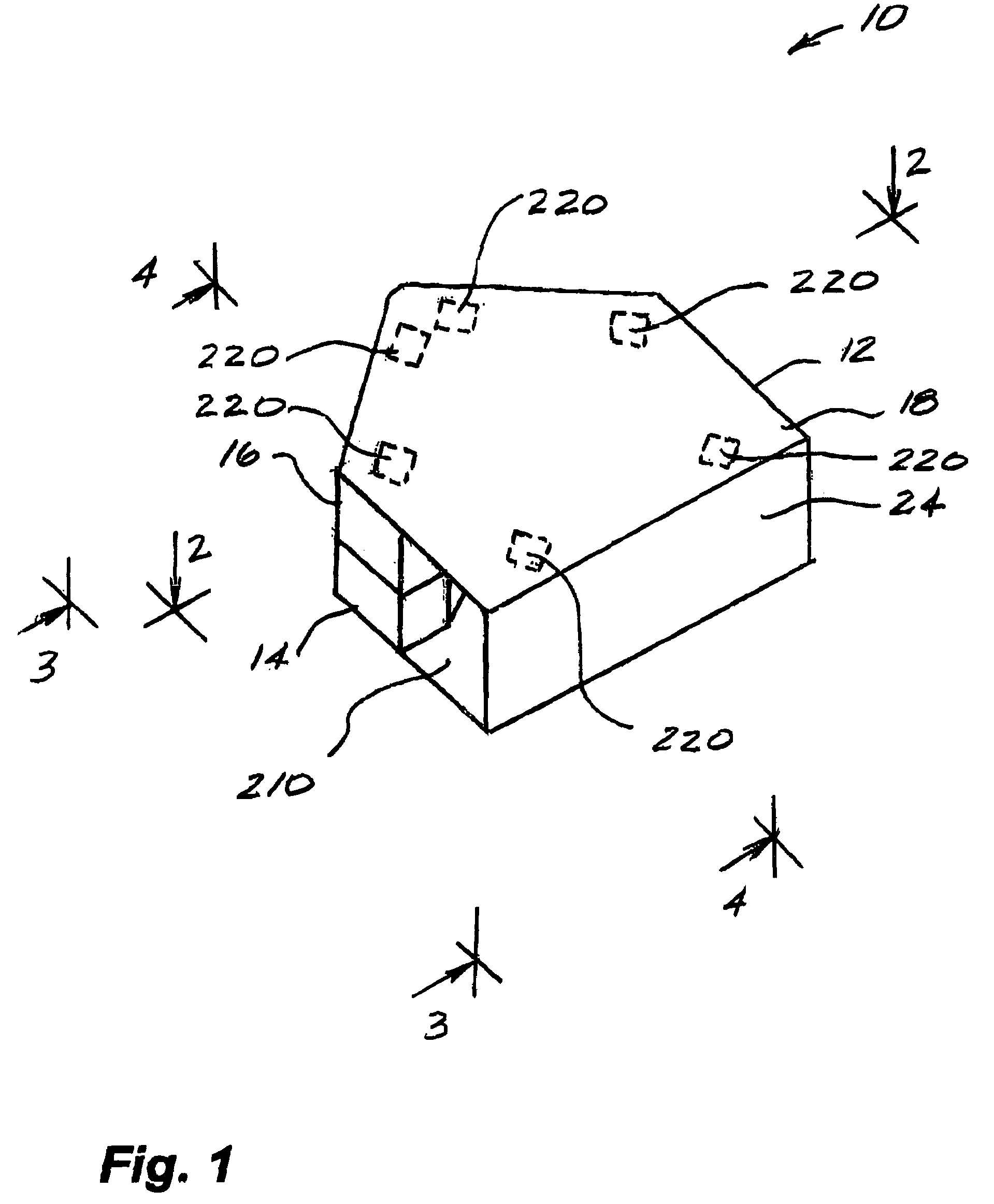
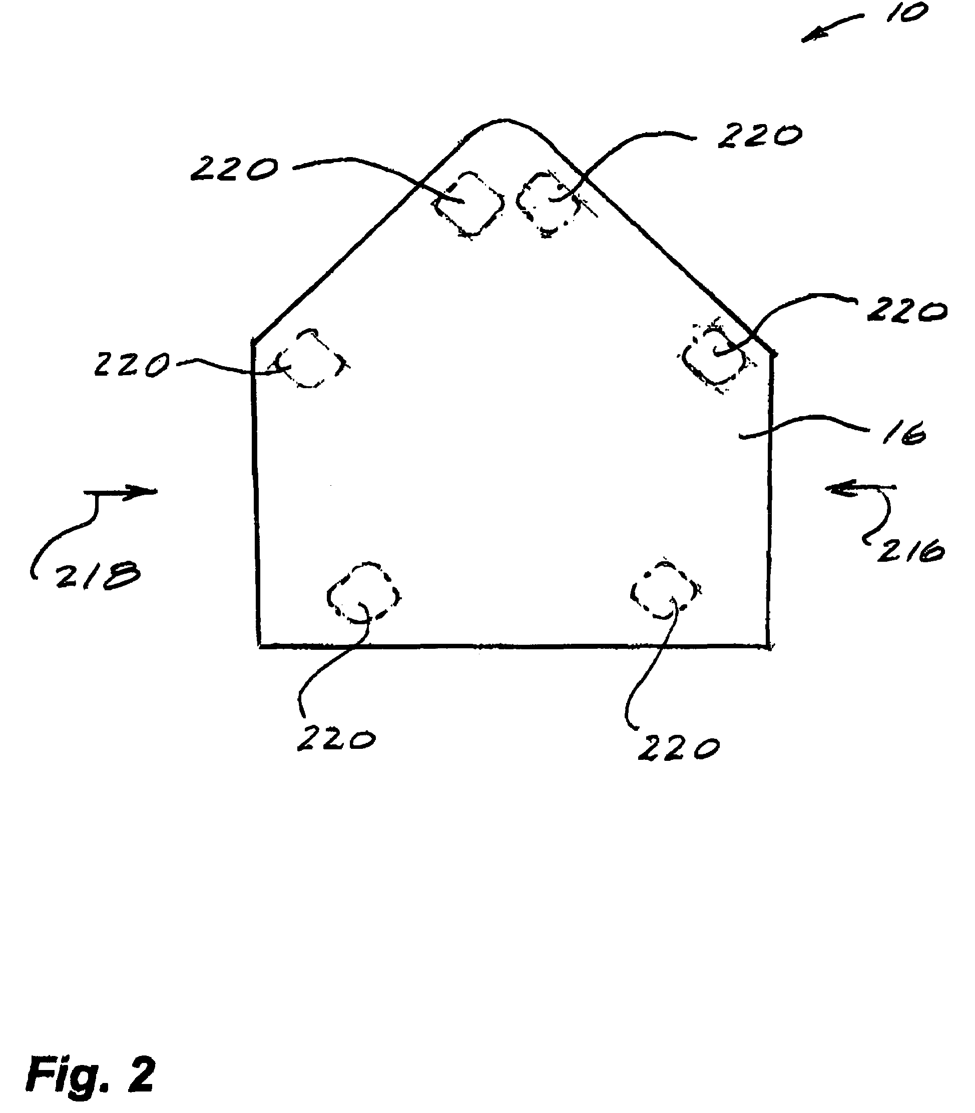
[0029]With reference to the drawings, there is shown in FIGS. 1-7 a rodent bait station 10 made in accordance with the present invention.

[0030]The rodent bait station 10 is formed as a single unitary member 12 portions 14, 16 of which are folded to form the assembled unit 18 shown in FIG. 1. A block of a rodenticide material 20 is positioned in a recess 22 which is formed in the unit 10 as shown in FIGS. 6 and 7. The unitary member 12 is formed as a molded or vacuum formed member having a plurality of recesses and projections which will be described presently.

[0031]As is shown in FIG. 6, the bait station 10 includes the first portion 14 and the second portion 16 which are connected by a flat intermediate portion 24.

[0032]The first portion 14 includes a first platform 26 and a second platform 28. The first platform 26 is supported by the walls 30, 32, 34, 36, 48. The walls 30, 36 incline inwardly relative to the edges 66, 68 of the intermediate portion 24. The walls 34, 32 incline to...


PUM


Abstract

A bait station is formed of a single unitary member which is folded to bring a first portion into contact with a second portion. An intermediate portion connects the first and second portions. The bait station includes a pair of passageways which lead from opposite edges of the bait station to a central recess portion. A block of rodenticide material is located in the recess portion and the passageways are angled to prevent access to the rodenticide material by children.

Description

FIELD OF THE INVENTION[0001]The present invention relates generally to the field of pest control and more particularly, to a rodent bait station.BACKGROUND OF THE INVENTION[0002]The prior art related to pest control includes the following U.S. patents.[0003]U.S. Pat. No. 2,953,868 to Chambers for a Device for Safely Administering Poison to Insects, Rodents and the Like, shows a poison carrying base which is connected to a protective cover. An opening between the base and the cover allows insects and rodents to eat the poison while preventing children from getting at the poison.[0004]U.S. Pat. No. 4,658,536 to Baker for a Bait Station, shows a device with the overall configuration of a capital letter H. Openings are provided at the ends of the arms of the H and bait containing bins are located on either side of the central connecting passageway between the arms of the H. The location of the bait containing bins makes access by children difficult.[0005]U.S. Pat. No. 4,841,669 to Demar...

Claims


Application Information

Patent Timeline
IPC IPC(8): A01M25/00
CPCA01M25/004
Inventor FRISCH, STEVEN
Owner FRISCH STEVEN
Why Eureka
Try Eureka