Heat exchanger with header and flow guide

a heat exchanger and flow guide technology, applied in the direction of indirect heat exchangers, stationary plate conduit assemblies, lighting and heating apparatus, etc., can solve the problems of reduced thermal performance, additional thermal stress on the apparatus, and the piping of the plate heat exchanger in this case becomes very complex and expensive, so as to achieve the effect of preventing the formation of separation swirls on the edge of the block

Inactive Publication Date: 2010-03-02
LINDE AG
View PDF27 Cites 0 Cited by
  • Summary
  • Abstract
  • Description
  • Claims
  • Application Information

AI Technical Summary

Benefits of technology

[0009]This configuration of the headers and especially of the fluid connection makes it possible to provide fluid connections on the two opposing sides of the heat exchanger block. Often, it is even possible to configure the plate heat exchanger such that all fluid connections are located on the same side of the heat exchanger block. The pipelines for delivering and withdrawing the material flows that have been brought into heat exchange with one another therefore need no longer be routed around the heat exchanger block in a complex manner. The piping cost is greatly reduced. The header is used not only for distributing the supplied fluid flow to the heat exchange passages or for collecting the fluid emerging from the heat exchange passages, but also for delivering and withdrawing the corresponding fluid flows.
[0012]Within the framework of the present invention, it has been found that separation swirls that lead to an uneven distribution of flow in the passages can occur at the fluid connection, and thus at the transition between the pipeline and the header on the edge of the heat exchanger block. This uneven distribution can lead to reduced thermal performance and also to additional thermal stresses on the apparatus. According to the present invention, in the entry fitting, on the end of the pipeline on which the fluid connection is located, there is a flow guide. Surprisingly, such a relatively economical flow guide in the entry fitting makes it possible to keep the separation swirls away from the passages and to thus greatly improve the uniform distribution in the header.
[0019]In embodiments, a flow guide facing the heat exchanger block may comprise a plate that ends on one edge of the heat exchanger block or in its vicinity, and the center axis of the pipeline may run through the block-side end of the flow guide. Accordingly, the formation of separation swirls on the edge of the block may be effectively prevented.

Problems solved by technology

The piping of the plate heat exchanger in this case becomes very complex and expensive.
This uneven distribution can lead to reduced thermal performance and also to additional thermal stresses on the apparatus.

Method used


Image

  • Heat exchanger with header and flow guide
  • Heat exchanger with header and flow guide
  • Heat exchanger with header and flow guide

Examples


Embodiment Construction

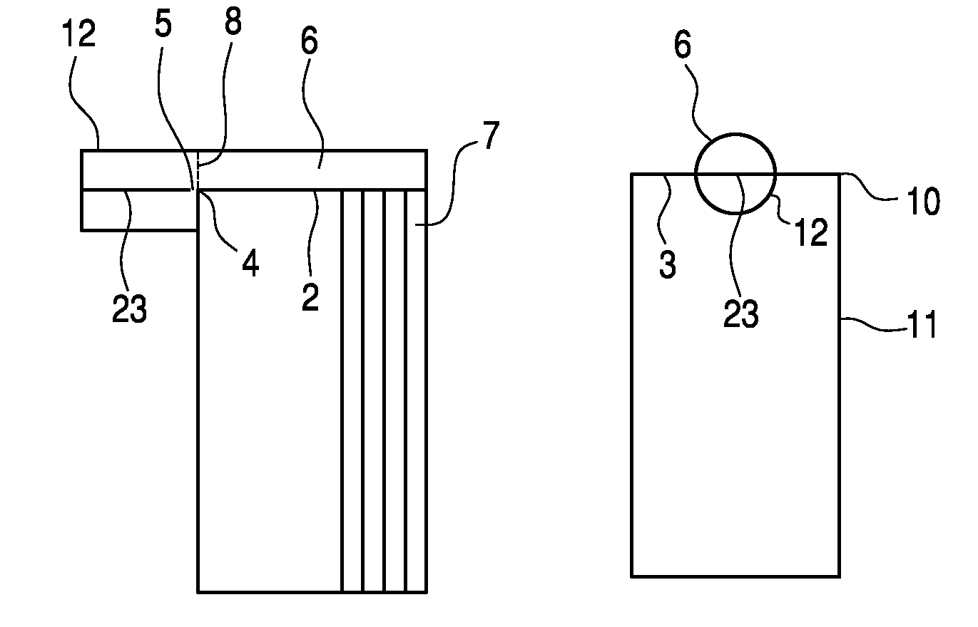
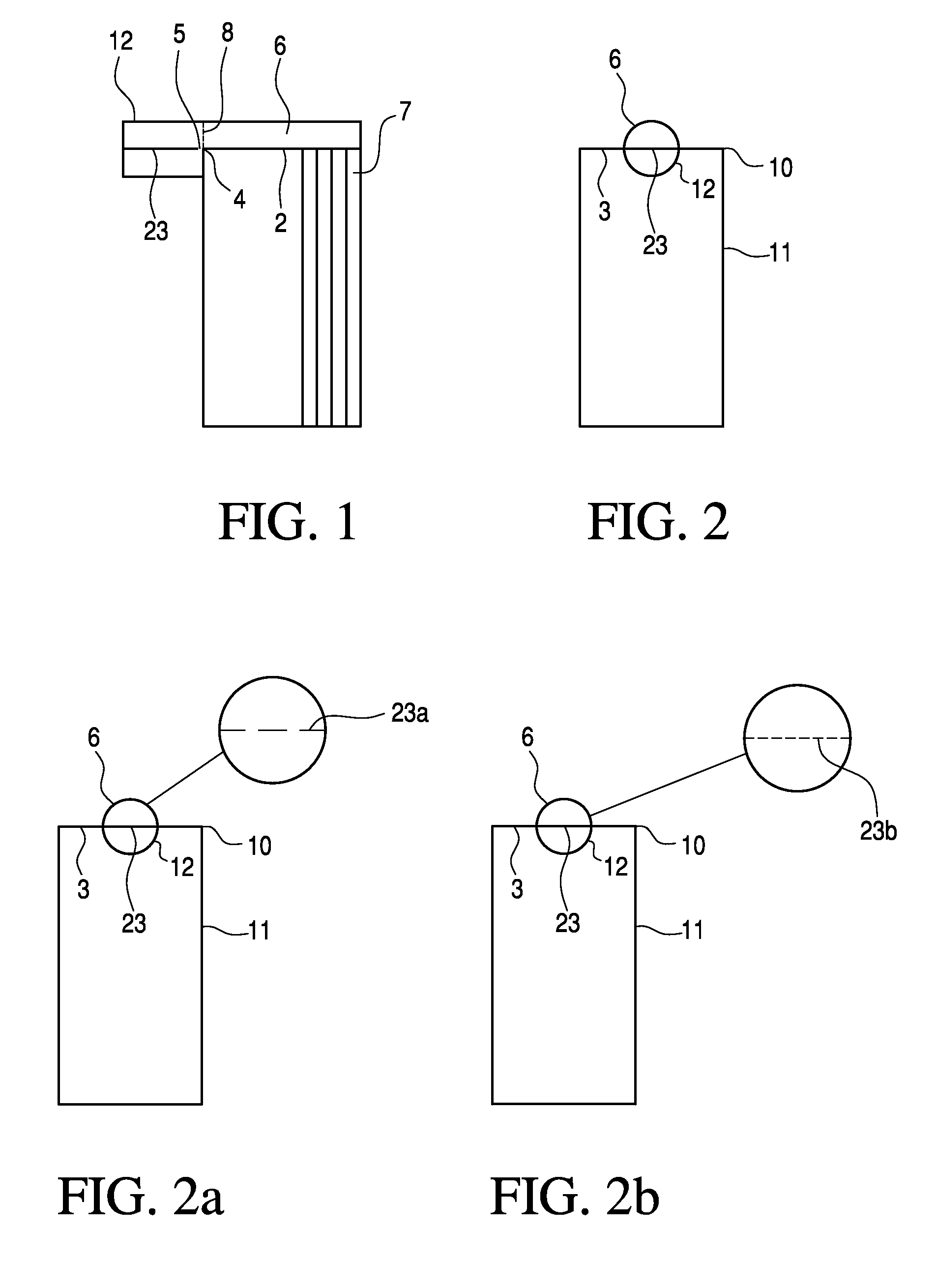
[0027]FIGS. 1 and 2 schematically show a plate heat exchanger in two directions of viewing that are perpendicular to one another. In the embodiment, the plate heat exchanger has one heat exchanger block 1 with a plurality of heat exchange passages 7 (for the sake of clarity only some of heat exchange passages are shown). The entry openings of one group of heat exchange passages are located in the area 2 of the top wall 3 of the heat exchanger block 1. A semi-cylindrical header 6 is welded to the top wall 3 and overlaps the entry openings. Of course, the heat exchanger block may have other headers and entry and exit openings not shown in the drawings. In embodiments, the header 6 may also be located along one edge 10 and / or on one wide side 11 of the block 1.

[0028]The header 6 may comprise a semi-cylindrical shell with a base surface 8. The base surface 8 comprises the “fluid connection.” At this point, the header 6 is connected to a pipeline 12 via which in operation the fluid that ...


PUM


Abstract

A plate heat exchanger includes a heat exchanger block having a plurality of heat exchange passages. On the heat exchanger block, a header is mounted that extends over at least one part of one side of the heat exchanger block and establishes a flow connection between the heat exchange passages. The plate heat exchanger is provided with a fluid connection, which is formed by the header-side end of a pipeline. The fluid connection is essentially perpendicular to the side of the heat exchanger block over which the header extends. Within the pipeline directly in front of the header, there is a flow guide.

Description

BACKGROUND AND SUMMARY OF INVENTION[0001]This application claims priority of German Patent Application No. 102005055676.0 filed Nov. 22, 2005, the disclosure of which is incorporated by reference in its entirety.[0002]The present invention relates to a plate heat exchanger with a heat exchanger block that has a plurality of heat exchange passages. On the heat exchanger block, a header is mounted that extends over at least one part of one side of the heat exchanger block and establishes a flow connection between part of the heat exchange passages. The header is provided with a fluid connection located essentially perpendicular to the side of the heat exchanger block over which the header extends.[0003]The heat exchanger block of a plate heat exchanger comprises several layers of heat exchange passages that are each bounded by separating sheets against one another. Terminal strips and cover sheets form the outer frame of the heat exchanger block. Within one layer, there can be other s...

Claims


Application Information

Patent Timeline
Patent Type & Authority Patents(United States)
IPC IPC(8): F28F9/02
CPCF28D9/00F28F9/0265F28F9/0246F28F9/02F28D2021/0033
Inventor AIGNER, HERBERTENGL, GABRIELEHECHT, THOMASMOBUS, HELGEMOLLER, STEFANSUSSMANN, WOLFGANGWANNER, ALFRED
Owner LINDE AG
Why Eureka
Try Eureka