Solution mining and a crystallizer for use therein

a crystallizer and solution mining technology, applied in surface mining, coal gasification, borehole/well accessories, etc., can solve the problems of high cost of mining, large amount of expensive and exotic metals, and difficulty in raising the mine temperature above, so as to reduce the cost of surface pipes

Inactive Publication Date: 2013-09-26
101061615 SASKATCHEWAN
View PDF3 Cites 2 Cited by
  • Summary
  • Abstract
  • Description
  • Claims
  • Application Information

AI Technical Summary

Benefits of technology

[0013]Methods described herein produce saturated or nearly saturated brines from a mine. The brines are at high temperature, particularly at or above the rock temperature at the ore body. Saturated brine can simply be cooled to recover ore in a simple crystallizer plant, with barren brine from the crystallizers being reheated and returned to the mine to further dissolve potash from the ore body. This eliminates the need for expensive evaporation equipment and high operating costs associated with such equipment. Small amounts of water can be added to the heated brine to produce the amount of brine needed to replace ore dissolved from the mined area. This results in the dissolution of about 10% of the salt in the mined area. In a mine utilizing these methods, salt liberated from the ore (as the potash dissolves) can be deposited in the mined-out regions, so only minimal amounts of salt ever are brought to the surface.
[0033]Another advantage of the current systems and methods is the possibility of locating the production well or wells near a plant as a permanent installation. This reduces surface pipe cost. Two parallel holes or pipelines may be needed for the feed lines to the wells. Overall, the surface disruption to agriculture, etc., is minimal. The fact that there are no salt tailings is hugely significant in a potash mining operation.

Problems solved by technology

Conventional solution-mining systems present difficulties in raising the mine temperature above the temperature of the ore deposit, as well as obtaining fully saturated brines from the mine.
This tends to be the most expensive part of the mine, and uses large amounts of expensive and exotic metals.
Large amounts of steam are also required.
Use of such ponds rather than crystallization machinery is still an expensive process that requires careful management and expensive dredging equipment.
This method is also seasonal with no potential to recover any heat.

Method used


Image

  • Solution mining and a crystallizer for use therein
  • Solution mining and a crystallizer for use therein
  • Solution mining and a crystallizer for use therein

Examples


Embodiment Construction

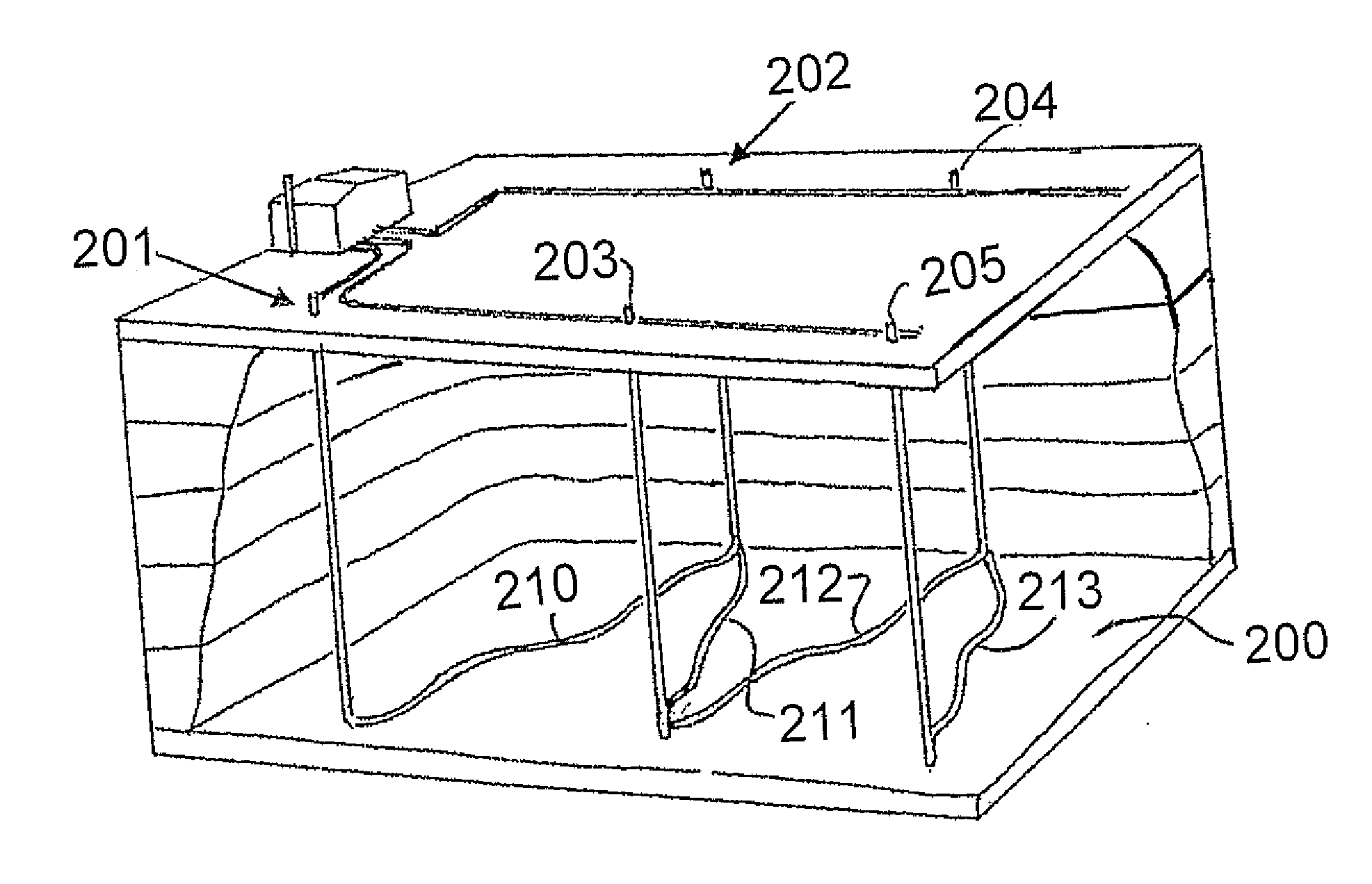
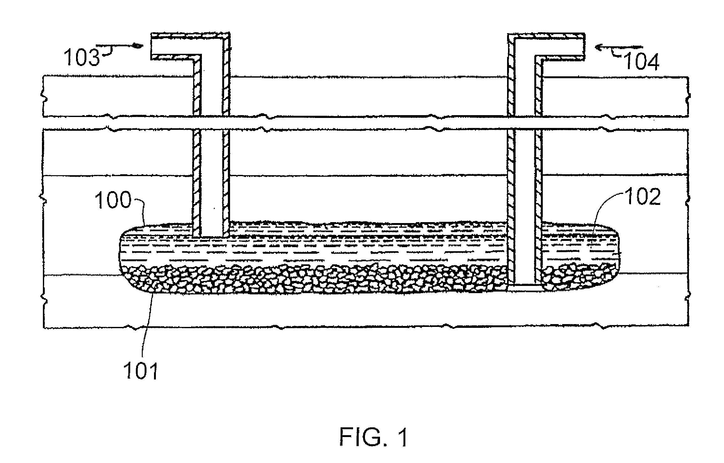
[0044]FIG. 1 shows and provides more detail of a conventional solvent-mining system as described above. The conventional solution mine creates individual caverns 100 by dissolving salt 101 from beneath the ore body 102 and rubblizing the ore into the cavern. Meanwhile, the ore is dissolved in a solution of fresh water or dilute brine 103 to form near-saturated solutions at temperatures equal to the temperature of the ore (or slightly higher). The caverns tend to develop vertically and, in some cases, connecting caverns. To recover the ore from the solution 104, evaporation and crystallization systems are necessary at the surface.

[0045]With a conventional solution-mining system, it is difficult to raise the mine temperature in the cavern 100 above the temperature of the ore. It is also difficult to obtain fully saturated brines in the solution 104. Thus, at the surface of a conventional system, ore (e.g., potash) concentration and temperature are increased using evaporators. These ev...


PUM


Abstract

In solution mining, holes are drilled parallel to the ground in the ore body to form a series of zigzag channels. These holes are connected to respective holes from the surface to provide a feed and delivery path and a solvent is circulated through the system so as to dissolve the ore and carry the ore to the surface. The flow of the solvent through the holes forms circular caverns at the intersection of the horizontal hole as well as meanders by eroding the holes so as to gradually extract the ore on each side of the hole. At the surface the ore is extracted in a series of crystallizers each formed by a vessel with an exterior cooling system and an internal wiping system providing shear inside the vessel. The solvent is topped up, reheated and returned to the paths to continue the process.

Description

CROSS-REFERENCE TO RELATED APPLICATION[0001]This application is a continuation of U.S. patent application Ser. No. 12 / 966,642, filed on Dec. 13, 2010, which claims priority to and the benefit of U.S. Provisional Patent Application No. 61 / 296,731, filed on Jan. 20, 2010, both of which are incorporated herein by reference in their respective entireties.FIELD[0002]This invention relates to methods for solution mining and to crystallizers for use in solution mining.BACKGROUND OF THE INVENTION[0003]In-situ leaching (ISL), also called in-situ recovery (ISR) or solution mining, is a process of recovering minerals such as copper and uranium through boreholes drilled into the ore deposit in the earth. The process initially involves drilling holes into the ore deposit. Explosive or hydraulic fracturing may be used to create open pathways in the deposit for solution to penetrate. Leaching solution is pumped into the deposit, where the solution contacts the ore. The leaching solution dissolves ...

Claims


Application Information

Patent Timeline
Patent Type & Authority Applications(United States)
IPC IPC(8): E21B43/28
CPCE21B43/28E21B43/40B01D9/0013Y02P10/20E21B43/35
Inventor HAUGEN, HARVEY
Owner 101061615 SASKATCHEWAN
Why Eureka
Try Eureka