Adjustable rigging system for a rowing boat

a rigging system and adjustable technology, applied in the field of rigging systems for rowing boats, can solve the problems of slipping brackets, difficult process, and potentially damaging process to riggers and boats

Inactive Publication Date: 2010-03-02
WINTER JONATHAN
View PDF6 Cites 6 Cited by
  • Summary
  • Abstract
  • Description
  • Claims
  • Application Information

AI Technical Summary

Benefits of technology

[0016]In other embodiments, the system further includes a cavity around at least one of the top and bottom hole, wherein at least one of the pitch adjusters is inserted at least partially within the cavity, and wherein the cavity retains the pitch member and prevents the pitch member from passing through the at least one hole. In some embodiments, the at least one of the pitch adjusters includes a flange, wherein the flange is larger than the support holes and prevents the entire pitch adjuster from passing through the support hole.

Problems solved by technology

However, it is a very difficult process which involves carefully bending the pin to the desired angle.
This process is also potentially damaging to the rigger and the boat as it relies on plastic deformation of the rigger.
Some of these riggers allow the adjustment of pitch, some do not.
One problem with this system is that over time, the bracket will slide and the pitch angle will change.
The other problem is that adjustment of this rigger requires a relatively high amount of skill, and ultimately is a waste of time for an athlete or coach.
Others of this second class of riggers do not allow any adjustment of pitch through simple methods as the bracket is attached to the rigger at a fixed pitch.
The oarlock inserts cited here only adjust pitch relative to the pin, and not the actual pitch of the pin itself, thus making it impossible to use these inserts to adjust outboard pitch without changing stern pitch.
This limitation further makes it impossible to both have the total oarlock pitch to change throughout the stroke cycle and to make the actual total change be adjustable and user selectable.
Thus, it is impossible with the Carter patent to both have total pitch change throughout the stroke cycle, and to adjust the total amount of change there is throughout the stroke cycle.

Method used


Image

  • Adjustable rigging system for a rowing boat
  • Adjustable rigging system for a rowing boat
  • Adjustable rigging system for a rowing boat

Examples


Embodiment Construction

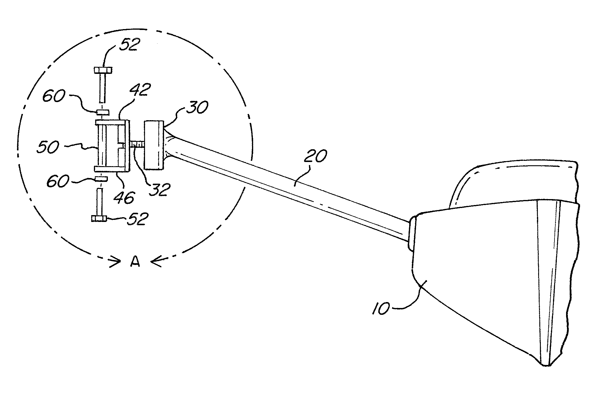
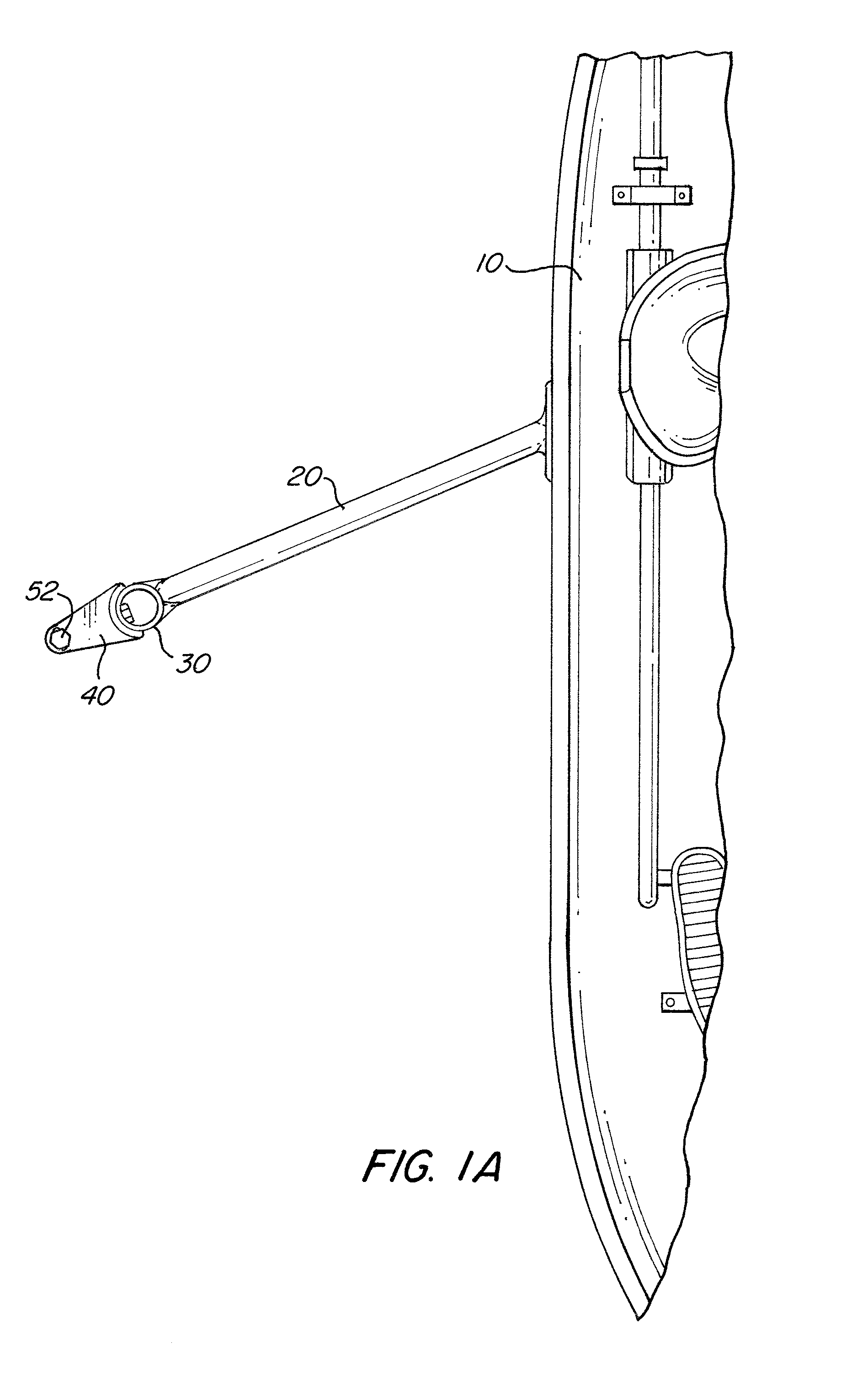
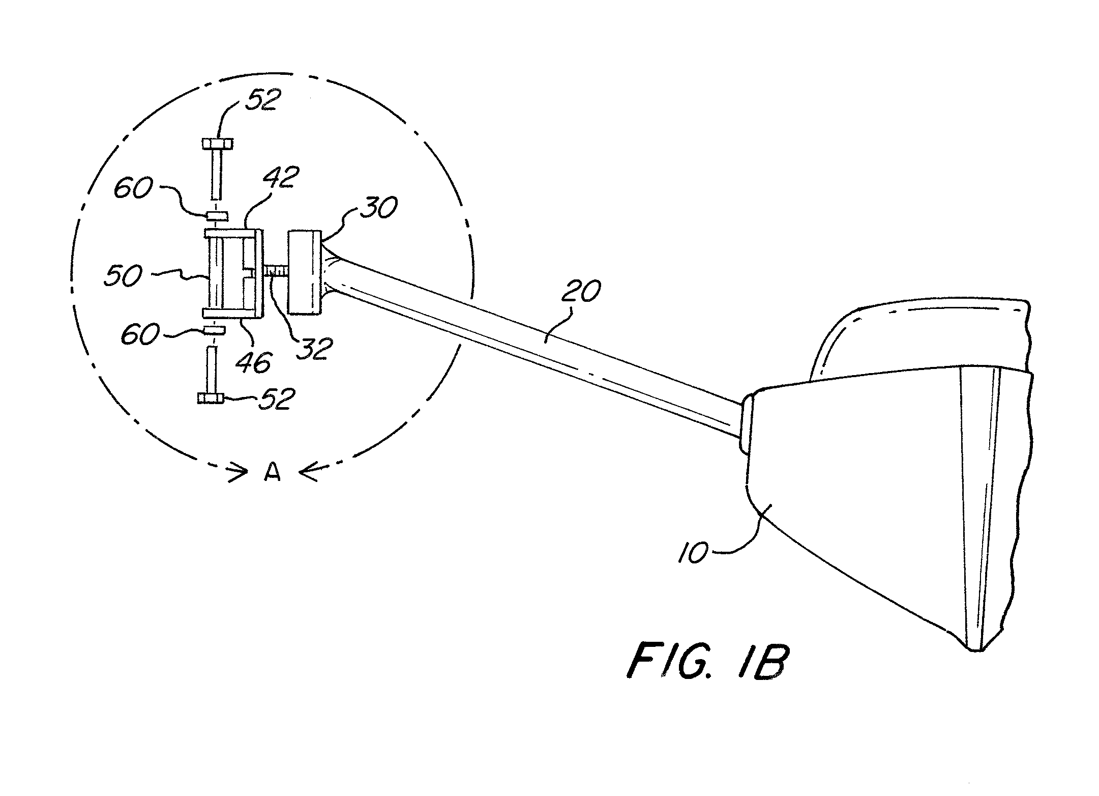
[0042]FIGS. 1A-3 illustrate a rigger or rigging system for a rowing boat 10 according to a first exemplary embodiment of the present invention. The rigging system includes a stay or stay mechanism 20 extending from the boat 10 to an outboard end portion 30. A bracket 40 including a top rigid support member 42 and a bottom rigid support member 46 is attached to the outboard end portion 30. The bracket 40 may be made in a variety of shapes capable of support a pin or other connection means from the top and bottom.

[0043]In the exemplary embodiment, the bracket 40 is secured to the outboard end portion 30 by a bolt 32. It should be noted however that the bracket 40 can be attached to the outboard portion 30 using a variety of methods. Some of the methods can be welding, adhesive, fasteners, bolts, contact geometry between the bracket 40 and the outboard end portion 30 (e.g., which prevents the bracket from rotating or sliding and thus changing the pitch), or a combination thereof. The i...


PUM


Abstract

An adjustable rigging system for a boat including a bracket adapted to connect to an outboard end portion of a stay mechanism for a boat, the bracket including a top hole and a bottom hole, wherein an axis is defined between a center of the top hole and a center of the bottom hole, a pin extending along the axis including two ends, each end removably connected to the bracket adjacent to one of the top and bottom holes, and wherein the location of at least one of the top and the bottom holes is adjustable to change a pitch of the axis and the pin.

Description

CROSS-REFERENCE TO RELATED APPLICATIONS[0001]This application claims priority benefits under 35 § U.S.C. 119(e) of the U.S. Provisional Application No. 60 / 892,368, filed on Mar. 1, 2007.FIELD OF THE INVENTION[0002]The invention relates to a rigging system for a rowing boat, and more specifically to a rigging system with means to adjust the pitch of pin in one or multiple directions.BACKGROUND OF THE INVENTION[0003]In the sport of rowing, there are rigid members attached to the side of a hull to hold a cylindrical pin at the appropriate distance from the boat. These are called riggers. An oar lock holds an oar and rotates around a pin. The main object of a rigger is to support the force generated by the user. An important feature in a rigger is its adjustability. Adjustability is important so that the rigging measurements may be customized to the user for optimal performance. One of the measurements many users desire to change is pitch. Pitch can be measured in two common ways, stern...

Claims


Application Information

Patent Timeline
Patent Type & Authority Patents(United States)
IPC IPC(8): B63H16/00B63B17/00B63H16/04B63H16/10
CPCB63H16/067B63H2016/063
Inventor WINTER, JONATHAN
Owner WINTER JONATHAN
Why Eureka
Try Eureka