Prosthesis for supporting a breast structure

a breast structure and prosthesis technology, applied in the field of breast structure prosthesis, can solve the problems of uneven or miss-cut mesh sheets, time-consuming and fastidious surgeons, uncomfortable patients, etc., and achieve the effect of lifting up breast tissue and significant thickness variations or fabric ridges

Active Publication Date: 2016-10-27
SOFRADIM PROD SAS
View PDF0 Cites 18 Cited by
  • Summary
  • Abstract
  • Description
  • Claims
  • Application Information

AI Technical Summary

Benefits of technology

[0240]Alternatively, the reinforcement part, the transition part and the fixation part, and in particular the first, second and third fabrics, are made as a single unitary structure. For example, using a knitting machine and the proper knitting pattern and / or yarn, the whole prosthesis, namely the reinforcement part, fixation part and transition part, and more particularly the first, second and third fabrics may be knitted and formed as a single unitary structure requiring no sewing or cutting. Such embodiment allows a very natural appearance as significant thickness variations or fabric ridges are thereby avoided.
[0241]In embodiments, a recess is provided in one or more of said reinforcement part, fixation part and transition part, said recess being intended to face the nipple-areola complex when the prosthesis is implanted. Such embodiments allow preserving the nipple-areola complex when a prosthesis of the invention is implanted in order to lift up breast tissue. Moreover, such embodiment allows facilitating the reconstruction of the nipple-areola complex further to the implantation of a breast implant and of the prosthesis of the invention. Indeed, the reconstruction of the nipple-areola complex usually takes place once the breast implant and the prosthesis of the invention are implanted and for example once cell colonization has already taken place. The presence of the recess in the prosthesis of the invention avoids an additional thickness in the area of the nipple-areola complex and leaves free said area. The surgeon does not have to take the prosthesis into account in this area when he proceeds to the reconstruction of the nipple-areola complex.

Problems solved by technology

Surgeons must take valuable time and cut the fabric sheet in the operating room during the procedure.
This is time-consuming and fastidious for the surgeon, and uncomfortable for the patient.
This need for cutting mesh fabric may result in uneven or miss-cut sheets of mesh which are then implanted and must be forcefully stretched or manipulated into a “fitted” engagement to the breast of the patient.
It may also happen that the surgeon has to fold parts of the mesh on itself, thereby creating additional thickness resulting in an improper fit around the curved area of the breast tissue or implant and possible painful feeling for the patient.
Folds may also cause unnatural appearance.
The lack of customized supporting prosthesis for breast implants can adversely effect the finished shape and feel of the reconstructed breast tissue.
Patients may suffer from discomfort from the material compressing the breast tissue or implant, or from a distaste for the visual aspects of the finished surgery.
Patients may require further surgeries to correct any inconsistencies with the mesh, or may just unfortunately live with the uncomfortable current state of the reconstruction.
Moreover, the conventional synthetic mesh materials used today make no provision for accommodating stretch in one or both directions on a controlled basis.
Known devices may therefore fail in providing adequate support and comfort in the natural movement and feel of the breast which for each human is of a custom dimension and area.
This poor fit and lack of elasticity may result in additional surgeries to correct such inconsistencies.
The stiffness of surgical mesh conventionally employed with breast reconstructive surgery can seriously inhibit the natural look, movement, and feel of the breast tissue and such is undesirable.
Further, stiff materials formed into meshes can prove more difficult to handle by the physician during implantation due to the need to customize the planar sheet, to fit the curved three dimensional shape of a breast.
Such misfitting sheets customized in the operating room may require additional suturing to maintain their position in the body.

Method used


Image

  • Prosthesis for supporting a breast structure
  • Prosthesis for supporting a breast structure
  • Prosthesis for supporting a breast structure

Examples


Embodiment Construction

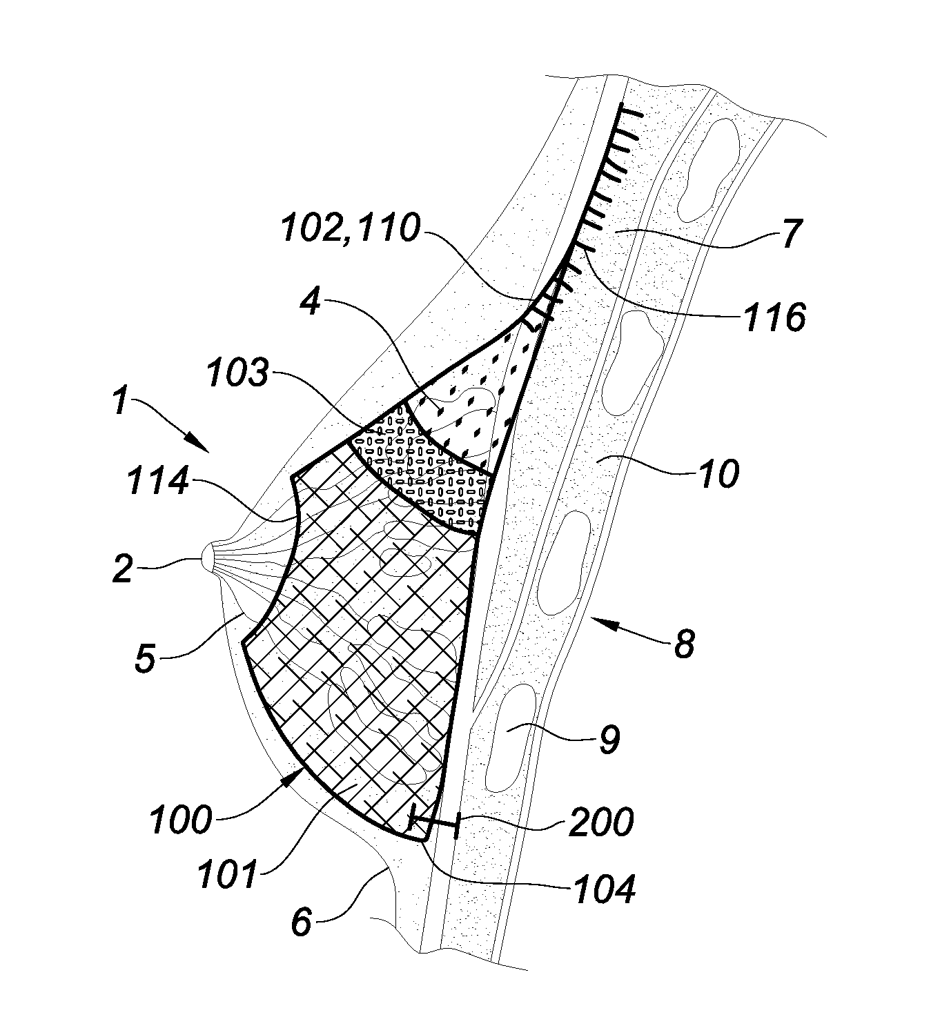
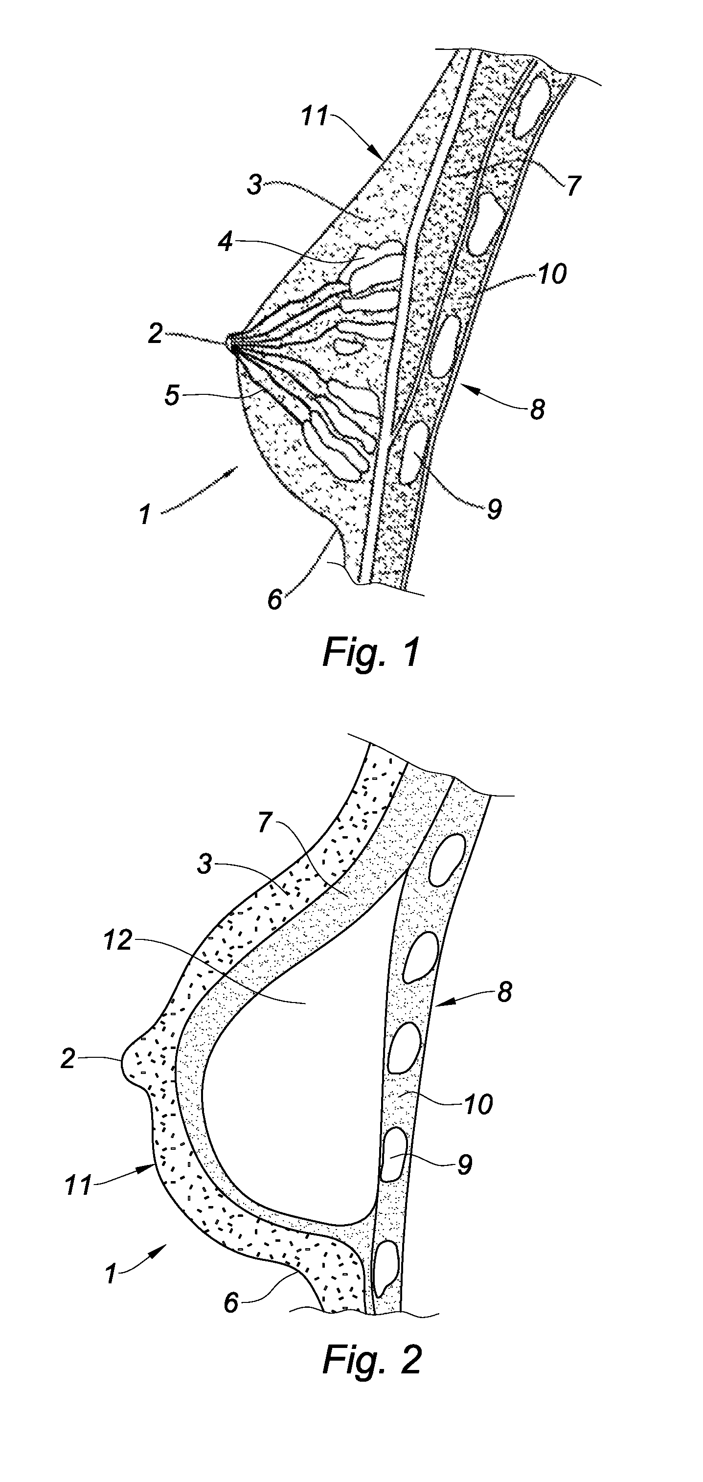
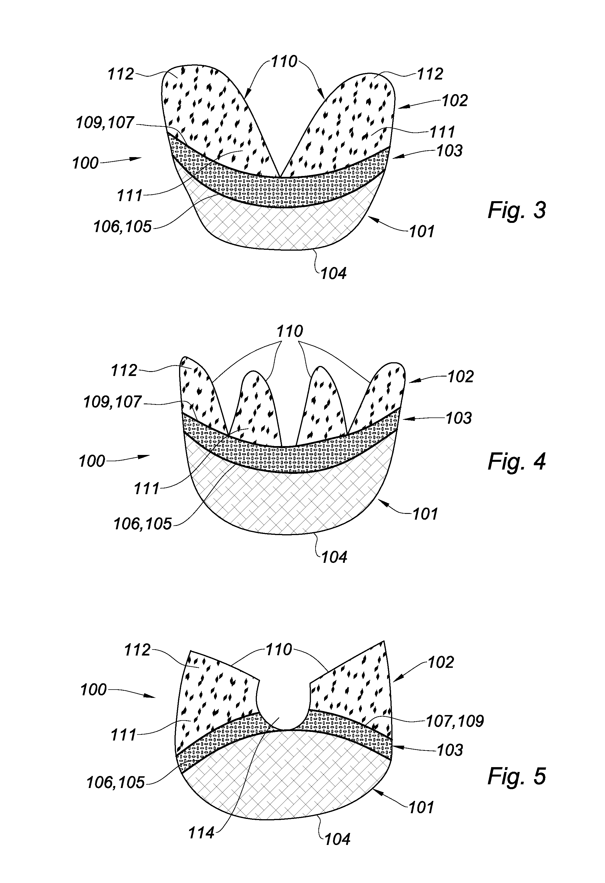
[0266]With reference to FIGS. 3-8 are shown embodiments of a prosthesis 100 of the invention. As will appear from the description below, the prosthesis 100 is intended to be implanted into a female patient in a view of supporting a breast implant 12 (see FIG. 10) in breast reconstruction post mastectomy or in a view of supporting breast tissue (see FIGS. 11 and 12) in breast lifting aesthetics surgery.

[0267]With reference to FIGS. 3-8, the prosthesis 100 comprises three parts, a reinforcement part 101, a fixation part 102 and a transition part 103. The reinforcement part 101 is configured to receive at least a curve-shaped lower portion of a breast structure and is intended to be sutured to the chest wall or to the infra-mammary fold. The fixation part 102 is intended to be fixed to the pectoral muscle. The fixation part 102 will usually be surrounding the top conical portion of the breast structure (see FIGS. 10 and 11). The transition part 103 connects the reinforcement part 101 t...


PUM


Abstract

The invention relates to a prosthesis for supporting a breast implant comprising:
    • a reinforcement part configured to receive a curved lower portion of a breast implant, the reinforcement part having an elongation under 50N in the vertical direction of E1,
    • a fixation part intended to be fixed to the pectoral muscle, the fixation part having an elongation under 50N in the vertical direction of E2, and
    • a transition part connecting together the reinforcement part and the fixation part, said transition part having an elongation under 50N in the vertical direction of E3,
    • wherein E3 is greater than E1 and greater than E2.

Description

CROSS-REFERENCE TO RELATED APPLICATIONS[0001]This application claims benefit of and priority to European Patent Application Serial No. 15305634.6 filed Apr. 24, 2015, the disclosure of the above-identified application is hereby incorporated by reference in its entirety.BACKGROUND[0002]1. Technical Field[0003]The present invention relates to a prosthesis for supporting a breast structure, such as a breast implant or breast tissue within a patient.[0004]2. Background of Related Art[0005]Breast cancer is one of the most common cancers among women. If the disease is not caught early, it is common that large portions of breast tissue are removed. In a conventional procedure called mastectomy, one or both breasts are partially or completely removed in order to treat or subsequently prevent breast cancer. Since such procedures generally result in a substantial amount of tissue being removed, many women will then opt for breast reconstructive surgery in order to reform the breast into a nat...

Claims


Application Information

Patent Timeline
Patent Type & Authority Applications(United States)
IPC IPC(8): A61F2/12
CPCA61F2/12A61F2250/0021A61F2250/0028A61F2/0063A61F2250/0018A61F2250/0063
Inventor DOUCET, GENEVIEVEBRUNE, THIERRYCOUDERC, XAVIERBEAUSSERON-VALENTIN, CECILE
Owner SOFRADIM PROD SAS
Why Eureka
Try Eureka