Grinding apparatus

a technology of grinding machine and grinding head, which is applied in the direction of grinding drive, grinding head, manufacturing tool, etc., can solve the problem and achieve the effect of large thickness variation of semiconductor wafer

Active Publication Date: 2021-08-05
DISCO CORP
View PDF9 Cites 1 Cited by
  • Summary
  • Abstract
  • Description
  • Claims
  • Application Information

AI Technical Summary

Benefits of technology

[0007]Consequently, while the semiconductor wafer is being ground by the grinding apparatus, the tilt of the chuck table tends to change, resulting in larger thickness variations of the semiconductor wafer.

Problems solved by technology

Consequently, while the semiconductor wafer is being ground by the grinding apparatus, the tilt of the chuck table tends to change, resulting in larger thickness variations of the semiconductor wafer.

Method used


Image

  • Grinding apparatus
  • Grinding apparatus
  • Grinding apparatus

Examples


Embodiment Construction

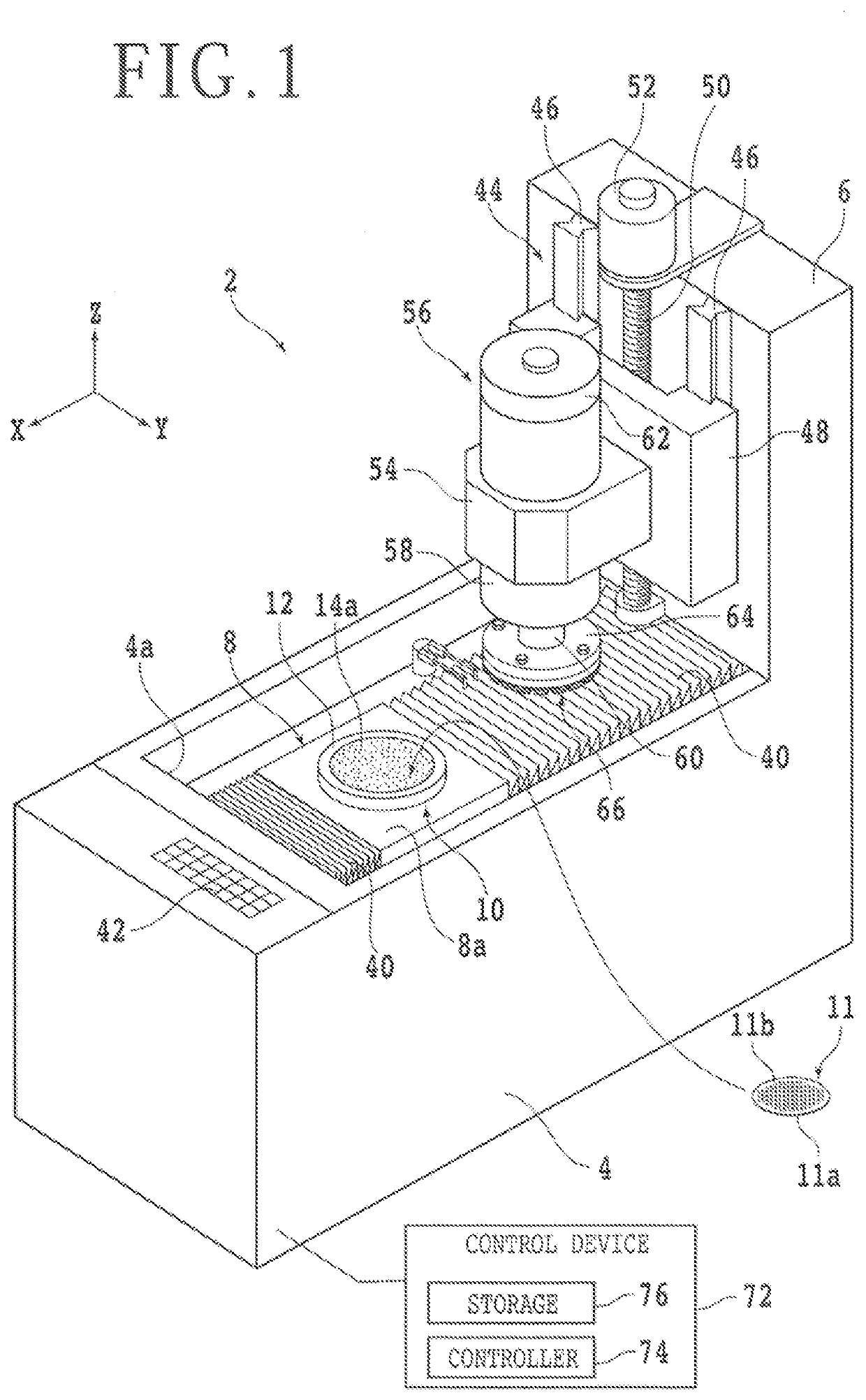
[0030]A grinding apparatus according to a preferred embodiment of the present invention will be described in detail below with reference to the accompanying drawings. FIG. 1 illustrates in perspective view a structural example of the grinding apparatus, denoted by 2. In FIG. 1, some components of the grinding apparatus 2 are illustrated as functional blocks. In FIG. 1, X-axis, Y-axis, and Z-axis directions represent directions perpendicular to each other. The Z-axis directions are also referred to as vertical directions, upward and downward directions, or grinding-feed directions.

[0031]The grinding apparatus 2 includes a base 4 on which the components of the grinding apparatus 2 are mounted. The base 4 has a rectangular opening 4a defined in an upper surface thereof and extending longitudinally along the X-axis directions. The opening 4a houses therein a ball-screw-type X-axis moving mechanism 8. The X-axis moving mechanism 8 has an unillustrated pair of guide rails extending along ...


PUM


Abstract

A grinding apparatus includes a chuck table for holding a workpiece thereon, a table base supporting the chuck table, a grinding unit for grinding the workpiece held on the chuck table with a grinding wheel mounted on an end of a spindle, a load detecting unit for detecting a load applied from the grinding unit to the table base, a tilt adjustment unit supporting the table base thereon, for adjusting a tilt of the table base, a storage for storing a correlative relation between loads applied to the table base and changes in the tilt of the table base, and a controller for controlling the tilt adjustment unit based on the load detected by the load detecting unit and the correlative relation, to adjust the tilt of the table base so that a change in the tilt of the table base that corresponds to the detected load is cancelled out.

Description

BACKGROUND OF THE INVENTIONField of the Invention[0001]The present invention relates to a grinding apparatus for grinding a workpiece and a grinding method for grinding a workpiece.Description of the Related Art[0002]Grinding apparatuses for grinding one surface of semiconductor wafers are used in the process of manufacturing semiconductor device chips. A grinding apparatus includes a chuck table for holding the other surface of a semiconductor wafer that is opposite the one surface thereof that is to be ground. A rotary actuator such as an electric motor for rotating the chuck table about its central axis, which is also referred to as a “rotational axis,” is disposed beneath a lower portion of the chuck table. The rotary actuator has a rotational shaft coupled to the lower portion of the chuck table. The chuck table has an upper surface as a projecting conical surface that functions as a holding surface for attracting the semiconductor wafer under suction.[0003]A grinding unit is d...

Claims


Application Information

Patent Timeline
Patent Type & Authority Applications(United States)
IPC IPC(8): B24B41/06B24B7/22B24B41/02
CPCB24B41/068B24B41/02B24B7/228B24B19/00B24B41/04B24B51/00B24B41/047B24B47/22H01L21/304B24B49/02
Inventor SUDO, YUJIRO
Owner DISCO CORP
Why Eureka
Try Eureka