A non-destructive testing method for the cutting edge of tunnel boring machine hob

A technology for tunnel boring machines and non-destructive testing, which is applied to instruments, uses sonic/ultrasonic/infrasonic waves to analyze solids, analyze materials, etc. It can solve the problem of difficulty in ensuring the progress of construction, high cost, and non-destructive testing of hob cutter rings to obtain internal defect information. The problem of unstable driving process of roadheader, etc., achieves the effect of reliable quality, stable performance and low cost

Active Publication Date: 2020-06-16
维尔特科创技术服务(北京)有限公司 +1
View PDF7 Cites 0 Cited by
  • Summary
  • Abstract
  • Description
  • Claims
  • Application Information

AI Technical Summary

Problems solved by technology

[0003] The purpose of the present invention is to propose a non-destructive testing method for the edge of the tunnel boring machine hob cutter ring, to solve the problem that the hob cutter ring in the prior art cannot achieve non-destructive testing to obtain internal defect information and further bring about the problem of the tunnel boring machine. The problem of unstable process, high cost, and difficulty in ensuring the construction progress of the project

Method used


Image

  • A non-destructive testing method for the cutting edge of tunnel boring machine hob
  • A non-destructive testing method for the cutting edge of tunnel boring machine hob
  • A non-destructive testing method for the cutting edge of tunnel boring machine hob

Examples


Embodiment Construction

[0033] Embodiments of the present invention will be further described below in conjunction with the accompanying drawings.

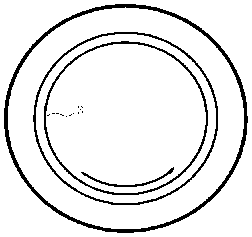
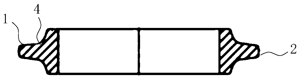
[0034] Due to its special structure and shape, the hob cutter ring has no testing procedures for this kind of test piece in China, and the technical difficulty is relatively high. According to the analysis and research of domestic peers, ultrasonic flaw detection alone is not enough to solve this technical problem, and ultrasonic and The two technologies of magnetic particle flaw detection are used together. The present invention adopts ultrasonic flaw detection technology in the flaw detection of the blade portion. Because the transition arc part is not the main working surface, the magnetic particle flaw detection technology can solve this technical problem.

[0035] See attached figure 1 And attached figure 2 , a kind of non-destructive testing method of the hob cutter ring edge 1 of the present invention is: respectively check the radial direction ...


PUM

PropertyMeasurementUnit
lengthaaaaaaaaaa
thicknessaaaaaaaaaa

Abstract

The invention discloses a nondestructive detection method for a blade part of a cutter ring of a rolling cutter of a tunnel boring machine, belongs to the technical field of nondestructive detection and aims at solving the problem that information of an internal defect of a cutter ring of a rolling cutter cannot be obtained and resulting problems of instability, high cost and the difficulty in ensuring project construction progress of a tunnel boring machine in the prior art. The detection method of the invention includes the following steps: fault detection is performed separately for four parts, including the radial part of the blade part of the cutter ring of the rolling cutter, the circumferential part of the outer circumference of the blade part, the circumferential part of the innerarc of the cutter ring, and the transition part of the end part and the blade part of the cutter ring; the detection range of the radial part of the blade part of the cutter ring is the range from theouter circumference of the cutter ring of the rolling cutter to 20mm of the cutter width, and the detection method is non-destructive fault detection using an ultrasonic fault detector; the detectionmethod of the circumferential part of the outer circumference of the blade part is non-destructive fault detection using the ultrasonic fault detector; the detection method of the circumferential part of the inner arc of the cutter ring is non-destructive fault detection using the ultrasonic fault detector; and the detection range of the tradition part of the end part and the blade part of the cutter ring is the part between 20mm and 30mm of the cutter width, and the detection method applies magnetic particle detection.

Description

technical field [0001] The invention belongs to the technical field of non-destructive testing, and in particular relates to a non-destructive testing method for the cutting edge of a hob cutter ring of a tunnel boring machine. Background technique [0002] The hob cutter ring is the key part of the cutter of the full-face tunnel boring machine, and plays a pivotal role in the tunnel boring process of the tunnel boring machine. Defects such as cracks, inclusions, folds, scars, layered fractures, non-metallic inclusions, carbide segregation, shrinkage tube residues, cracks, and uneven grains are not allowed inside the knife ring. Due to the existence of any one of the defects, the hob cutter ring will cause abnormal wear, curling, chipping and fracture of the hob cutter ring under extremely harsh working environments. The key area of ​​concern for ultrasonic volumetric flaw detection of disc hob cutters is the outer edge, which is the core area that undertakes the rock-break...

Claims


Application Information

Patent Timeline
Patent Type & Authority Patents(China)
IPC IPC(8): G01N29/04G01N27/84
CPCG01N27/84G01N29/04G01N2291/0289
Inventor 张凌张爱武孔祥权贺东泽方亮张秀秀
Owner 维尔特科创技术服务(北京)有限公司
Why Eureka
Try Eureka