Autostereoscopic pixel arrangement techniques

a pixel arrangement and autostereoscopic technology, applied in optics, instruments, electrical equipment, etc., can solve the problems of increased brightness, difficult fabrication, low brightness, etc., and achieve the effect of minimizing the resolution of the master imag

Inactive Publication Date: 2010-03-02
LEDOR LLC +1
View PDF19 Cites 11 Cited by
  • Summary
  • Abstract
  • Description
  • Claims
  • Application Information

AI Technical Summary

Benefits of technology

[0035]The present invention is a method and apparatus for providing an autostereoscopic display system. In an autostereoscopic display system, an interdigitated stereogram is generated and displayed on an electronic display. The display includes a lenticular screen over the surface of the display, which allows the user to observe the stereogram on the display and obtain a true stereoscopic effect.
[0036]In accord with the invention, the resolution of the master images is minimized and then the pixels from the master images are mapped to form a interdigitated stereogram. The optimum minimization of the resolution is obtained when the ratio of horizontal resolution to vertical resolution for the master images approximates the screen aspect ratio of the display. In this way, less computation is involved in remapping the pixels to form an interdigitated stereogram.

Problems solved by technology

The raster barrier is one approach that has benefits in terms of simplicity of fabrication and optical quality, but it suffers from low brightness.
While a lenticular screen is more difficult to fabricate than a raster barrier screen, it has greater brightness.
The look-around capability is of secondary importance, since the observer's mobility is usually limited.
Nevertheless, an examination of panoramagram images produced fifty years ago and those produced today shows no improvement in stereoscopic effect and image quality.
A disadvantage of this technique is that it requires a subject that does not move since the exposure takes place over a period many seconds.
Another comparison with van Berkel indicates that our techniques do not address the shape or other characteristics of the lenticular element.
Cathode ray tube displays, on the other hand, are usually not flat and the location of each pixel with exact specificity cannot be guaranteed.
In point of fact, in such a useful and important case, applying the Wood art would be inconvenient or impossible.
Happily, tipping the lenticules, as described by Winnek, reduces the visibility of the interstices.

Method used


Image

  • Autostereoscopic pixel arrangement techniques
  • Autostereoscopic pixel arrangement techniques
  • Autostereoscopic pixel arrangement techniques

Examples


Embodiment Construction

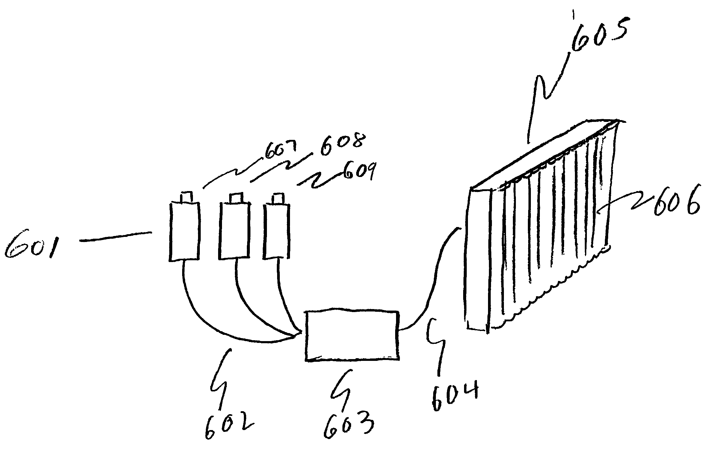
[0043]In the course of developing the present invention, we have applied the inventive techniques to both hardcopy prints and flat panel displays. In the case of prints, an Alps dye sublimation and Epson inkjet printers were used in conjunction with lenticular screens available off-the-shelf which were laminated to the surface of the print. As is typical, the lenticules were oriented parallel to the edge of the print, as in a traditional Ives' panoramagram. In the case of the flat panel display, we used a Silicon Graphics flat panel LC monitor with a 17-inch diagonal screen, and the technique disclosed by Winnek was used to increase horizontal resolution and reduce the moire patterns.

[0044]Our compression / decompression and pixel mapping schemes were used for both prints and flat panels. While we reduce the resolution of the master images, we do not reduce the pictorial image quality of the final autostereoscopic image. It is important to be able to reduce the resolution of the maste...


PUM


Abstract

An autostereoscopic display system wherein an interdigitated stereogram is generated and displayed on an electronic display. The display includes a lenticular screen over the surface of the display which allows the user to observe the stereogram on the display and obtain a true stereoscopic effect. In accord with the invention, the resolution of master images is minimized and then the pixels from the master images are mapped to form the interdigitated stereogram. The optimum minimization of the resolution is obtained when the ratio of horizontal resolution to vertical resolution for the master images approximates the screen aspect ratio of the display. In this way, less computation is involved in remapping the pixels to form an interdigitated stereogram.

Description

BACKGROUND OF THE INVENTION[0001]Autostereoscopic displays are stereoscopic displays that do not require eyewear selection devices. Such displays have been the subject of inventive scrutiny for almost a century. An important step was taken in 1908 with Lippmann's invention of integral or fly's-eye photography that resembles holography in its effect. Since then, numerous inventors have sought to create a binocular stereoscopic illusion using an optical selection technique located at the display surface (photographic print, motion picture screen, electronic display).[0002]The raster barrier is one approach that has benefits in terms of simplicity of fabrication and optical quality, but it suffers from low brightness. Another approach, attributed to Ives, is an offshoot of Lippmann's work, and uses a series of elongated lenslets or lenticules as a selection device. While a lenticular screen is more difficult to fabricate than a raster barrier screen, it has greater brightness. The lent...

Claims


Application Information

Patent Timeline
Patent Type & Authority Patents(United States)
IPC IPC(8): H04N13/04H04N13/139G02B30/27
CPCG02B27/2214H04N13/0404H04N13/0445H04N13/0239H04N13/0242H04N13/305H04N13/243H04N13/349H04N13/239H04N13/30G02B30/27H04N13/139
Inventor LIPTON, LENNYAKKA, ROBERT
Owner LEDOR LLC
Why Eureka
Try Eureka