
Electrophotographic photoreceptor for blue-violet exposure light source and electrophotographic imaging apparatus employing the photoreceptor

a photoreceptor and exposure light technology, applied in the field of electrophotographic imaging apparatus employing the photoreceptor, can solve the problems of inpractical use, difficulty in obtaining clear spots, beam diameter, etc., and achieve the effect of effectively producing printed images with high resolution and significant reduction of radiating light spots

Inactive Publication Date: 2006-12-28
SAMSUNG ELECTRONICS CO LTD
View PDF3 Cites 8 Cited by
  • Summary
  • Abstract
  • Description
  • Claims
  • Application Information

AI Technical Summary

Benefits of technology

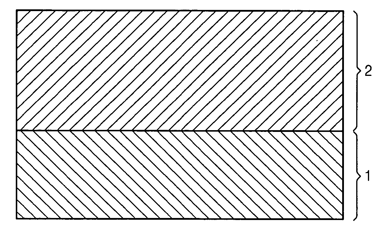
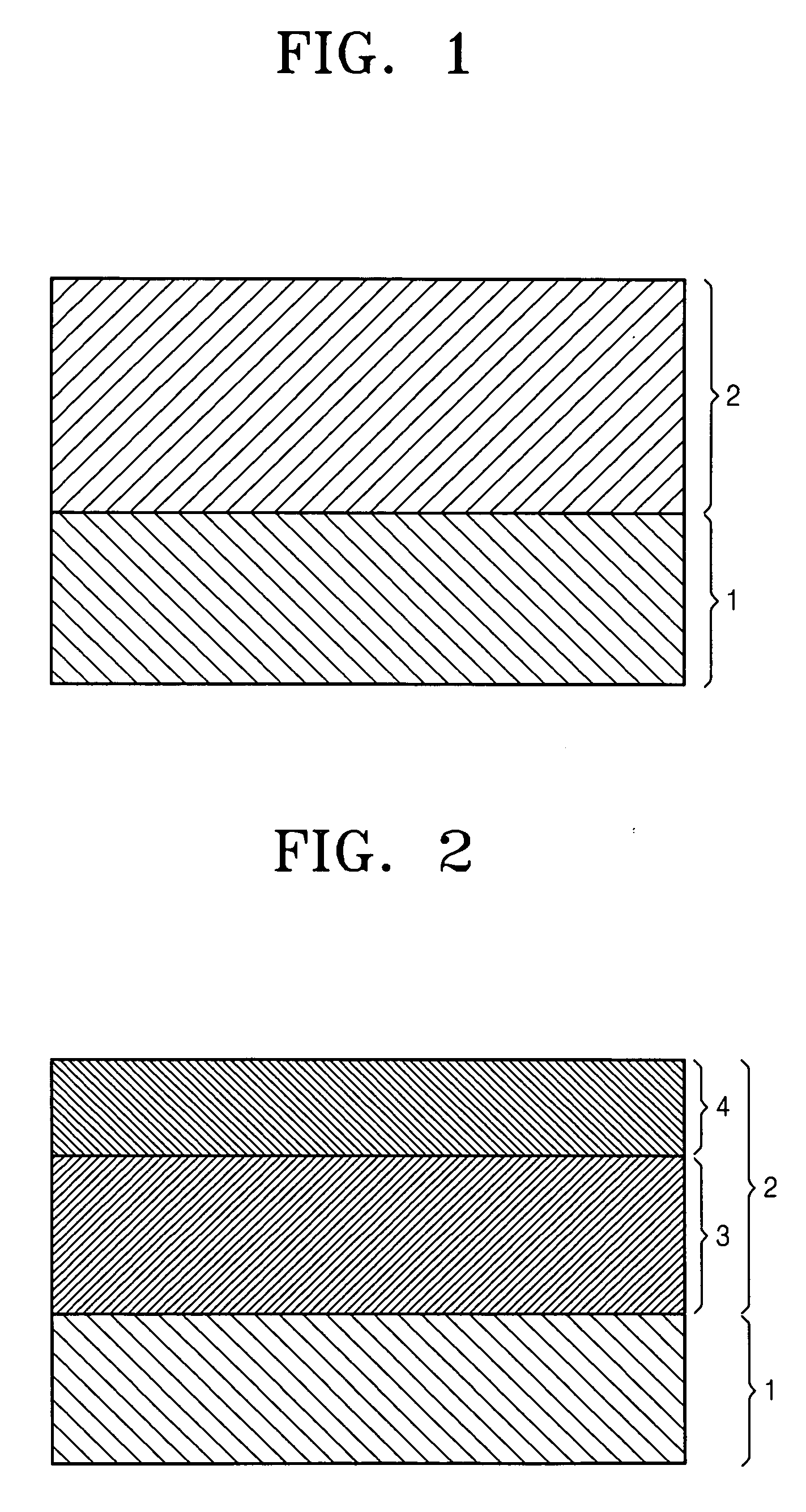
The present invention provides an electrophotographic photoreceptor that can produce high-resolution printed images even when using blue-violet light as an exposure light source. The photoreceptor includes a photosensitive layer with a charge generating material and a charge transporting material dispersed or dissolved in a binder resin. The light transmittance of the photosensitive layer is set in a predetermined range to minimize resolution degradation and provide good photosensitive and mechanical properties. The electrophotographic imaging apparatus includes the electrophotographic photoreceptor and a charging apparatus, a light exposure apparatus, and a developing apparatus. The use of blue-violet light as the exposure light source reduces the dispersion of radiating light spots and effectively produces printed images with high resolution.

Problems solved by technology

However, in semiconductor lasers having a near-infrared oscillation wavelength, which is widely being used as an exposure light source, it is difficult to obtain clear spot by decreasing the beam diameter because of diffraction limit of the laser.
In 1991, ZnSe laser emitting at 450 nm was introduced, but was not been practically used due to its short lifetime.
However, rapid degradation due to, for example, corona discharging, or the deterioration of the mechanical durability thereof may occur.
However, when the electrophotographic photoreceptor having a photosensitive layer at the surface which includes a charge generating material together with a charge transporting material as disclosed in Japanese Laid-Open Patent Application Hei 9-240051 is applied to an electrophotographic imaging apparatus using a blue-violet light source, it was shown that the electrophotographic imaging apparatus cannot provide printed images with sufficient high resolution than had been expected, since the amount of the charge generating material in the surface layer is small, the radiated light may penetrate inside the photosensitive layer to some extent, and then is scattered and dispersed.
Moreover, in the blue-violet light range, since the charge transporting material as well as charge generating material absorb light, the amount of light absorption cannot be controlled by simply adjusting the amount of the charge generating material.
Thus, effective light energy is reduced due to the light absorption by the acceptor compound so that the photosensitivity is insufficient in the blue-violet light range.

Method used


Image

  • Electrophotographic photoreceptor for blue-violet exposure light source and electrophotographic imaging apparatus employing the photoreceptor
  • Electrophotographic photoreceptor for blue-violet exposure light source and electrophotographic imaging apparatus employing the photoreceptor
  • Electrophotographic photoreceptor for blue-violet exposure light source and electrophotographic imaging apparatus employing the photoreceptor

Examples


example 1

[0057] 2 parts by weight of α-titanyl phthalocyanine and 2 parts by weight of polycarbonate Z resin (PANLITE TS-2020, Teijin Kasei Co.) were mixed with 46 parts by weight of chlorobenzene. The mixture was milled for an 1 hour using a sand mill to be finely dispersed.

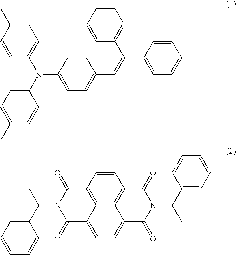
[0058] parts by weight of arylamine-based compound (1), as a hole transporting material, 15 parts by weight of naphthalenetetracarboxylic acid diimide-based compound (2), as an electron transporting material, and 50 parts by weight of polycarbonate Z resin were dissolved in 300 parts by weight of chloroform.

[0059] The dispersion and the solution were mixed at a weight ratio of 1:8. The mixture was dispersed to be homogeneous using a homogenizer, thereby obtaining a coating slurry for forming the photosensitive layer. The coating slurry was applied on an anodized aluminum drum (anodic oxide layer thickness: 5 μm) having a diameter of 30 mm using a ring bar and then dried, thereby obtaining a monolayer type electrophoto...

example 2

[0060] A photoreceptor drum was manufactured using the same method of Example 1 except that the weight ratio of the dispersion and the solution was 1:4. The measured light transmittance at a wave length of 405 nm was 5.5×10⁻².

example 3

[0061] 40 parts by weight of the arylamine-based compound (1) as a hole transporting material, 60 parts by weight of polycarbonate Z resin were dissolved in 300 parts by weight of chloroform, thereby obtaining a solution for forming the charge transporting layer. The solution was applied on an anodized aluminum drum (anodic oxide layer thickness: 5 μm) having a diameter of 30 mm using a ring bar, and then dried, thereby obtaining charge transporting layer having a thickness of about 8 μm.

[0062] The dispersion and the solution used in Example 1 were mixed at a weight ratio of 1:2, thereby obtaining a dispersion for forming the charge generating layer. Next, the dispersion was applied on the charge transporting layer using the ring bar, and then dried, thereby forming a charge generating layer having a thickness of about 7 μm.

[0063] The light transmittance of the obtained multilayer type electrophotographic photoreceptor drum at a wavelength of 405 nm was 8.9×10⁻².


PUM


Abstract

An electrophotographic photoreceptor and an electrophotographic imaging apparatus employing the photoreceptor are disclosed. The electrophotographic photoreceptor includes an electrically conductive substrate and a photosensitive layer formed on the electrically conductive substrate, wherein a latent image is formed on the photosensitive layer using a blue-violet exposure light source having a wavelength of 380 to 450 nm. The outer surface of the photosensitive layer includes a charge generating material, a charge transporting material, and a binder resin. The light transmittance of the photosensitive layer is 1.0×10⁻¹ to 1.0×10⁻³ in the light exposure wavelength. The electrophotographic photoreceptor can provide high quality images with high resolution using the blue-violet exposure light source.

Description

CROSS-REFERENCE TO RELATED PATENT APPLICATION [0001] This application claims the benefit of Korean Patent Application No. 10-2005-0055939, filed on Jun. 27, 2005, in the Korean Intellectual Property Office, the disclosure of which is incorporated herein by reference in its entirety. BACKGROUND OF THE INVENTION [0002] 1. Field of the Invention [0003] The present invention relates to an electrophotographic photoreceptor and an electrophotographic imaging apparatus employing the photoreceptor. More particularly, the invention is directed to an electrophotographic photoreceptor using blue-violet light as an exposure light source to obtain high resolution and an electrophotographic imaging apparatus employing the photoreceptor. [0004] 2. Description of the Related Art [0005] From the early days, AlGaAs / GaAs semiconductor lasers having oscillation wavelengths in a near-infrared region near 800 nm have been widely used as an exposure light source in electrophotographic imaging apparatuses....

Claims


Application Information

Patent Timeline
Patent Type & Authority Applications(United States)
IPC IPC(8): G03G5/047
CPCG03G5/047G03G5/0605G03G5/0672G03G5/0614G03G5/0651G03G5/0609G03G5/04G03G5/06142
Inventor YOKOTA, SABUROKIM, BEOM-JUNMAKINO, MOTOLEE, HWAN-KOOKIM, SEUNG-JULEE, JI-YOUNG
Owner SAMSUNG ELECTRONICS CO LTD
Learn More