Mobility support via routing

a technology of mobility support and routing, applied in the field of wireless communications, can solve the problems of reducing coverage, high cost, and reducing the number of access points, and achieve the effect of increasing the received signal strength

Inactive Publication Date: 2010-03-02
AVAGO TECH INT SALES PTE LTD
View PDF126 Cites 23 Cited by
  • Summary
  • Abstract
  • Description
  • Claims
  • Application Information

AI Technical Summary

Benefits of technology

[0007]A communication system is described. In one embodiment, the communication system comprises a mobile station having a transmitter to transmit packets wirelessly according to a protocol and multiple repeaters communicably coupled with the mobile station. Each of the plurality of repeaters receives one or more packets of the wirelessly transmitted packets from the mobile station. Each of the repeaters receives an indication of which of the wirelessly transmitted packets were received without errors by other repeaters and a received signal strength for those packets. Each of the repeaters sends an acknowledgement packet to the mobile device for packets received at a higher received signal strength than any other repeater. The communication system also includes a switch coupled to the repeaters. Each repeater forwards to the switch wirelessly transmitted packets.

Problems solved by technology

There are a number of problems associated with the current implementations of 802.11 networks.
Also, the cost of each of the access points is approximately $500.00.
Generally, such a high cost is a deterrent to having a large number of access points.
However, by reducing the number of access points, coverage diminishes and the 802.11 network is less effective.
Furthermore, there are a number of mobility problems associated with the current 802.11 network deployments.
However, these schemes do not work effectively as there is no standard solution in place and users haven't indicated a desire for long-term proprietary solutions.

Method used


Image

  • Mobility support via routing
  • Mobility support via routing
  • Mobility support via routing

Examples


Embodiment Construction

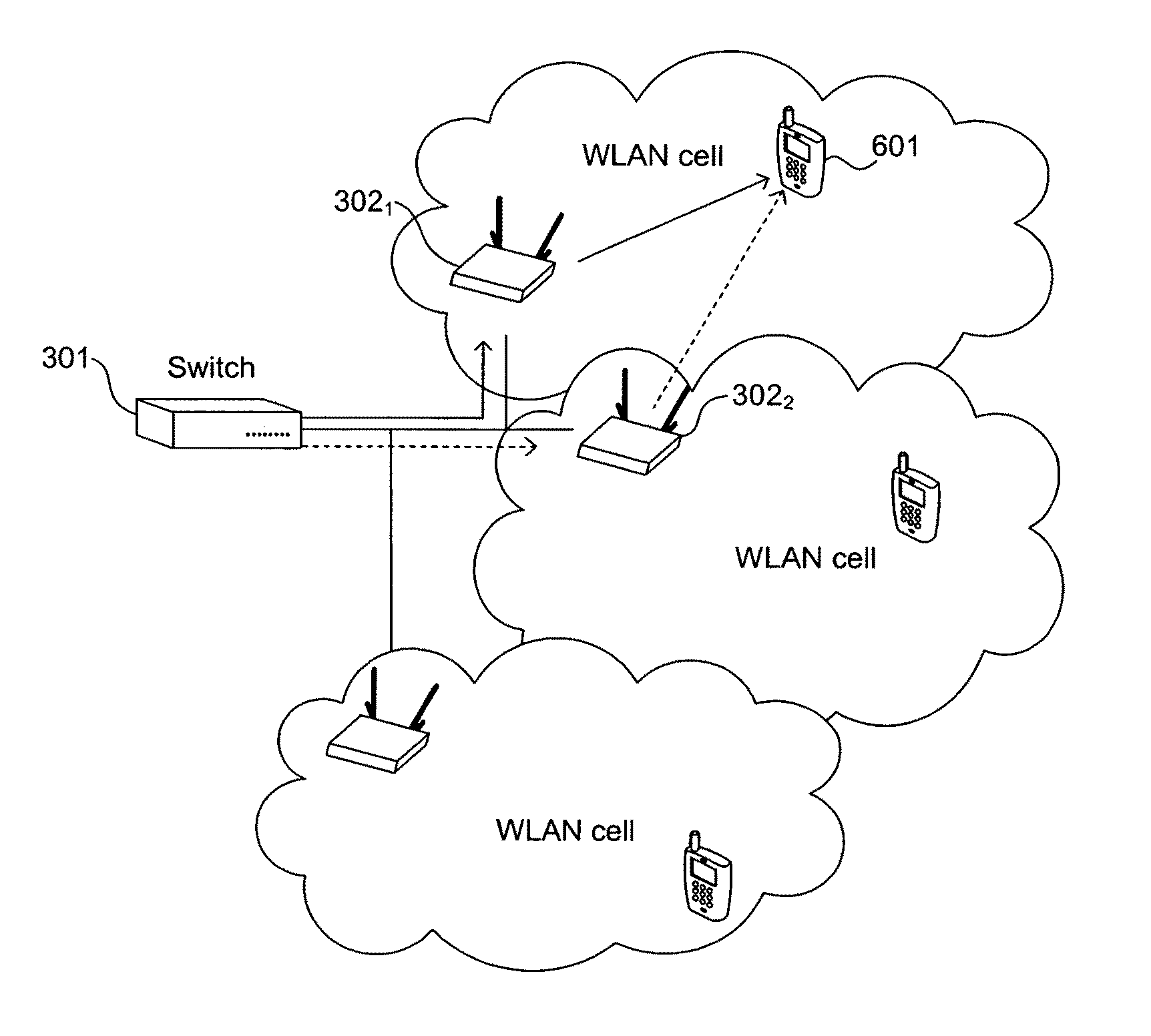
[0026]A communication system is described. In one embodiment, the communication system comprises a mobile station having a transmitter to transmit packets wirelessly according to a protocol and multiple repeaters communicably coupled with the mobile station. Each of the plurality of repeaters receives one or more packets of the wirelessly transmitted packets from the mobile station. Each of the repeaters receives an indication of which of the wirelessly transmitted packets were received without errors by other repeaters and a received signal strength for those packets. The communication system also includes a switch coupled to the repeaters. Each of the repeaters forwards to the switch each packet of the wirelessly transmitted packets that each repeater had received at a received signal strength higher than any other repeater.

[0027]In the following description, numerous details are set forth in order to provide a thorough understanding of the present invention. It will be apparent, ...


PUM


Abstract

A communication system is described. In one embodiment, the communication system comprises a mobile station having a transmitter to transmit packets wirelessly according to a protocol and multiple repeaters communicably coupled with the mobile station. Each of the plurality of repeaters receives one or more packets of the wirelessly transmitted packets from the mobile station. Each of the repeaters receives an indication of which of the wirelessly transmitted packets were received without errors by other repeaters and a received signal strength for those packets. The communication system also includes a switch coupled to the repeaters. Each of the repeaters forwards to the switch each packet of the wirelessly transmitted packets that each repeater had received without errors at a received signal strength higher than any other repeater.

Description

RELATED APPLICATIONS[0001]This is a divisional of, and claims priority to, U.S. patent application Ser. No. 10 / 044,480, filed on Jan. 11, 2002 now U.S. Pat. No. 6,760,318, entitled “Receiver Diversity In A Communication System”, assigned to the corporate assignee of the present invention.FIELD OF THE INVENTION[0002]The present invention relates to the field of wireless communications; more particularly, the present invention relates to receiver diversity in a wireless communications system.BACKGROUND OF THE INVENTION[0003]FIG. 1 illustrates an exemplary network environment used today. Referring to FIG. 1, a corporate Local Area Network (LAN) backbone 102 interfaces to a number of desktop computers 1031-103n and may interface to Internet 101. Corporate LAN backbone 102 may comprise a firewall 102A, corporate server 102B, and a standard Ethernet switch 102C. Ethernet switch 102C includes an interface by which desktops 1031-1031n are coupled to the corporate LAN backbone 102 and may ac...

Claims


Application Information

Patent Timeline
Patent Type & Authority Patents(United States)
IPC IPC(8): H04W4/00H04L1/00H04L1/16H04L12/18H04L12/28H04L12/56
CPCH04L1/16H04L45/00H04W88/04H04W88/12H04L12/189H04L2001/0097H04W28/04H04W36/08H04W40/00H04W40/02H04W80/00H04W84/12
Inventor BIMS, HARRY
Owner AVAGO TECH INT SALES PTE LTD
Why Eureka
Try Eureka