
An optimization method and device for an IRS-assisted wireless communication system

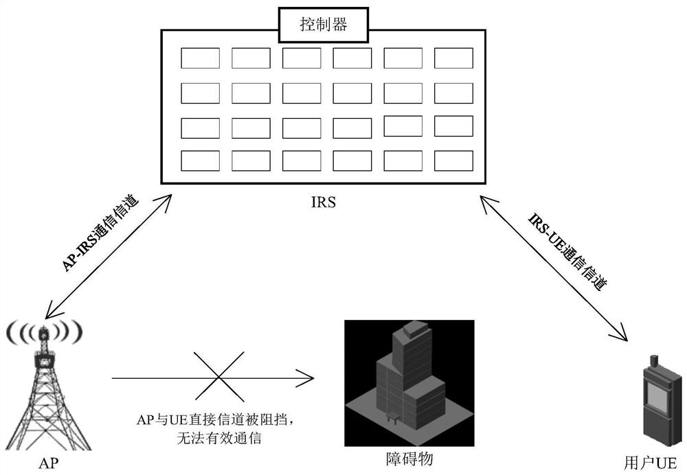
A technology of a wireless communication system and an optimization method, applied in the field of optimization of a wireless communication system, can solve problems such as the reflection coefficient matrix is ​​not ideal, the communication effect between AP and UE is not ideal, and the position estimation error is large, so as to achieve high accuracy and improve the received signal Intensity, the effect of improving spectral efficiency

Active Publication Date: 2020-12-08
HUAZHONG UNIV OF SCI & TECH
View PDF4 Cites 1 Cited by
  • Summary
  • Abstract
  • Description
  • Claims
  • Application Information

AI Technical Summary

Problems solved by technology

[0005] Aiming at the defects of the prior art, the purpose of the present invention is to solve the problem that when the position of the UE is constantly changing in the prior art, the error of the RUS in estimating the position of the UE is large, resulting in the reflection coefficient matrix not being the most suitable matrix, and the communication effect between the AP and the UE. suboptimal technical issues

Method used


Image

  • An optimization method and device for an IRS-assisted wireless communication system
  • An optimization method and device for an IRS-assisted wireless communication system
  • An optimization method and device for an IRS-assisted wireless communication system

Examples


Embodiment Construction

[0054] In order to make the object, technical solution and advantages of the present invention clearer, the present invention will be further described in detail below in conjunction with the accompanying drawings and embodiments. It should be understood that the specific embodiments described here are only used to explain the present invention, not to limit the present invention. In addition, the technical features involved in the various embodiments of the present invention described below can be combined with each other as long as they do not constitute a conflict with each other.

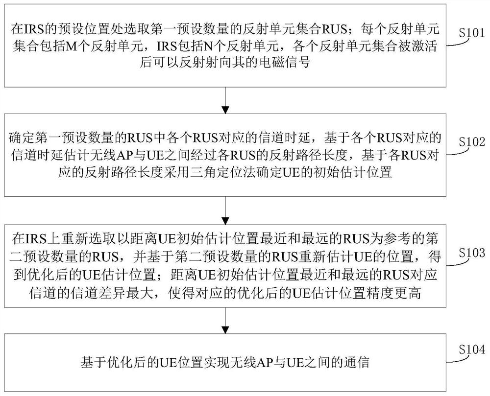
[0055] image 3 A flowchart of an optimization method for an IRS-assisted wireless communication system is provided for the present invention, such as image 3 shown, including the following steps:

[0056] S101, select a first preset number of reflective unit sets RUS at a preset position of the IRS; each reflective unit set includes M reflective units, the IRS includes N reflective units, an...


PUM


Abstract

The invention discloses a method and device for optimizing an IRS-assisted wireless communication system. The method comprises the steps of selecting a first preset number of reflection unit sets RUSat the preset position of an IRS; determining a channel time delay corresponding to each RUS in the first preset number of RUSs, estimating a reflection path length distance passing through each RUSbetween the wireless AP and UE based on the channel time delay corresponding to each RUS, and determining an initial estimation position of the UE by using a triangulation positioning method based on the reflection path length corresponding to each RUS; re-selecting a second preset number of RUSs taking the RUSs closest to and farthest from the initial estimated position of the UE as reference on the IRS, and re-estimating the position of the UE to obtain an optimized UE estimated position; with the channel difference corresponding to the RUS closest to the initial estimated position of theUE and the channel difference corresponding to the RUS farthest from the initial estimated position of the UE are maximum, so that the precision of the optimized estimated position of the UE is higher; and communicating based on the optimized UE position. According to the invention, the position of the UE can be accurately estimated, and the communication between the AP and the UE is optimized.

Description

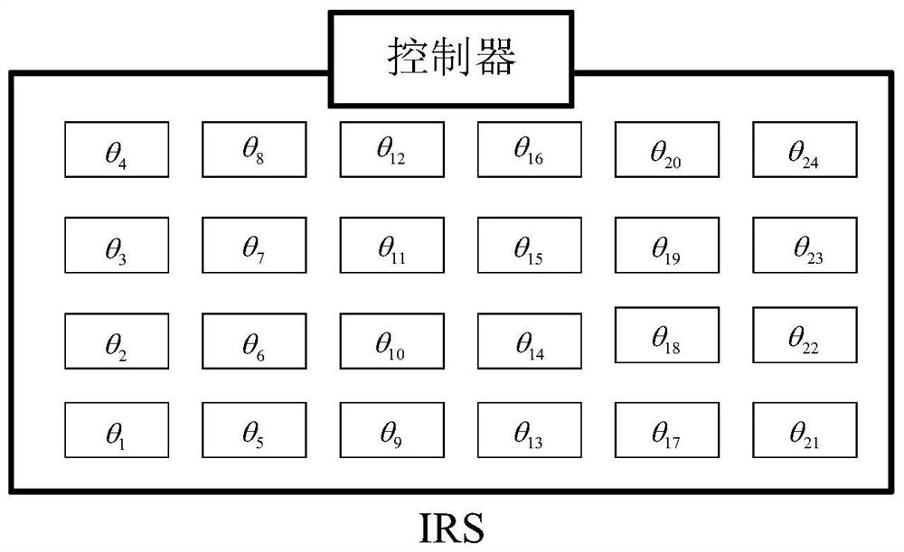
technical field [0001] The present invention relates to the technical field of 5G wireless communication, and more specifically, to an optimization method and device for an IRS-assisted wireless communication system. Background technique [0002] In the field of 5G wireless communication, because the transmission of high-frequency signals (such as millimeter waves or terahertz waves) is easily blocked by obstacles, the effect of wireless communication is not good. In order to solve this problem, there is an idea: through a specially manufactured low-cost, passive, reflective, reconfigurable smart surface (Metasurface / LIS / Large Intelligent Surface / Reconfigurable reflectarrays / Intelligent walls / Software-controlled metasurfaces / Intelligent Reflecting Surface / IRS, hereinafter are expressed by IRS), especially when the wireless access point AP (Access Point) and the user equipment UE (User Equipment) cannot communicate directly, they can communicate through the AP-IRS-UE channel...

Claims


Application Information

Patent Timeline
Patent Type & Authority Patents(China)
IPC IPC(8): H04W4/02H04W24/02H04W64/00
CPCH04W4/02H04W24/02H04W64/00
Inventor 尹海帆徐雄崔耀燊
Owner HUAZHONG UNIV OF SCI & TECH
Learn More