Transflective display panel and display apparatus using the same

a display panel and display panel technology, applied in non-linear optics, instruments, optics, etc., can solve the problems of insufficient utilization of portable terminals in any location, inability to achieve high utilization of lcd, and inability to see the display degrade, so as to achieve constant out-coupling efficiency

Inactive Publication Date: 2010-03-09
SAMSUNG DISPLAY CO LTD
View PDF4 Cites 10 Cited by
  • Summary
  • Abstract
  • Description
  • Claims
  • Application Information

AI Technical Summary

Benefits of technology

[0016]The present invention provides a display panel and a display apparatus using the same, which can provide high-brightness color reproduction by enhancing reflection brightness and adjusting white balance.
[0020]The diffraction grating of the subpixel may include patterns which provide a constant out-coupling efficiency, which is defined as the product of the transmittance of the sub color filter and the diffraction efficiency of the diffraction grating.

Problems solved by technology

In this case, the visibility of the display may degrade, because the brightness of an LCD screen is relatively dark.
Therefore, the advantage of the portable terminals in their ability to be used in any location cannot be sufficiently exploited.
In addition, when the LCD is used for a demonstration display, an outdoor billboard, or in a public place where illumination is present, high utilization of the LCD cannot be obtained if sufficient visibility is not secured.
Furthermore, when the reflection mode is implemented using the external light, the light passes through the color filter 50 two times, resulting in degradation of the light efficiency.
However, because the scattering pattern 45 scatters and reflects the incident light, the direction of the reflected light is uncontrolled and scattered.
Therefore, an amount of light condensed at a user's viewing angle is so small that brightness is low.
Although the white balance can be adjusted by varying the size of the light hole h in red, green and blue pixels, increasing the front brightness with high reflection is limited.

Method used


Image

  • Transflective display panel and display apparatus using the same
  • Transflective display panel and display apparatus using the same
  • Transflective display panel and display apparatus using the same

Examples


Embodiment Construction

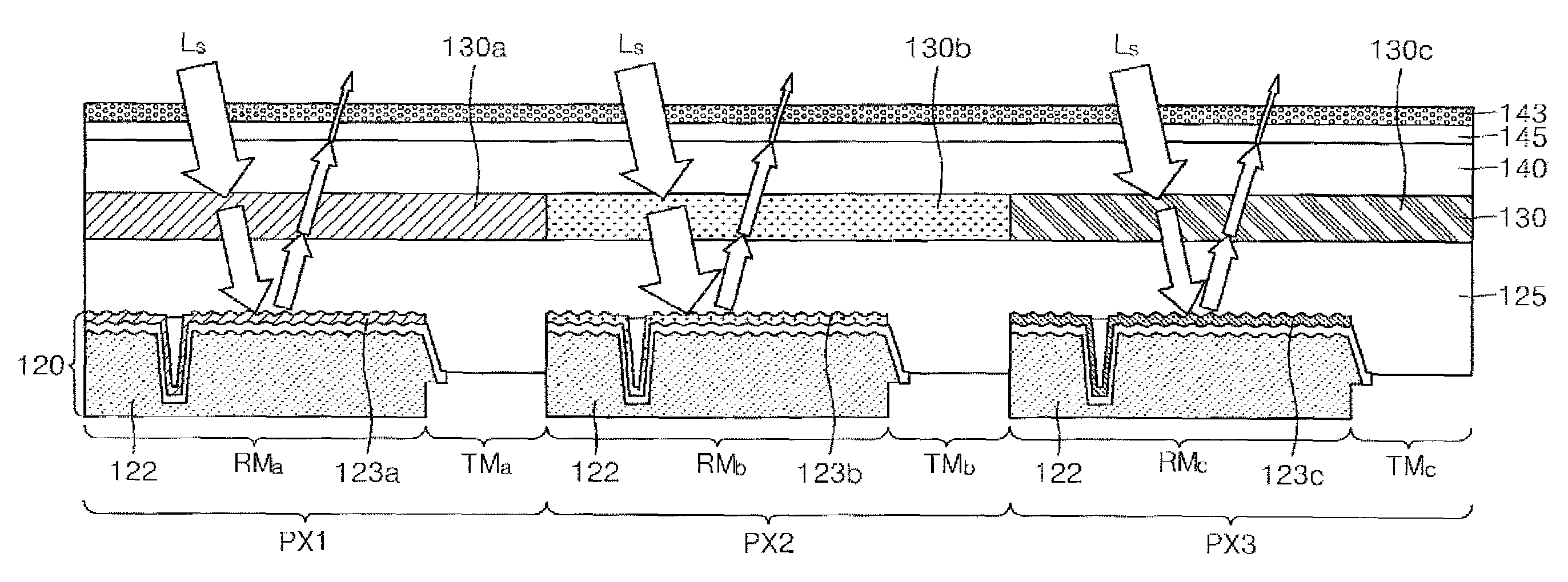
[0050]FIG. 4 is a cross-sectional view of one pixel having a plurality of subpixels emitting light of different colors. The pixel includes a first subpixel PX1, a second subpixel PX2, and a third subpixel PX3. The first to third subpixels PX1, PX2 and PX3 are arranged in a matrix form. A transflective display panel according to an exemplary embodiment of the present invention includes a transflective mode region 120 having reflection mode regions RMa, RMb and RMc and transmission mode regions TMa, TMb and TMc in the subpixels PX1, PX2 and PX3, respectively. The reflection mode regions RMa, RMb and RMc include diffraction gratings 123a, 123b and 123c, respectively. A reflection mode is implemented in the reflection mode regions RMa, RMb and RMc to form an image using an external light Ls, and a transmission mode is implemented in the transmission mode regions TMa, TMb and TMc to form an image using light emitted from a light source of a display apparatus.

[0051]Specifically, FIG. 4 is...


PUM

PropertyMeasurementUnit
peak wavelengths λP1aaaaaaaaaa

Abstract

A transflective display panel and a display apparatus using the same are provided. The display panel includes a plurality of pixels arranged in a matrix. Each of the pixels includes a plurality of subpixels, and each subpixel within a pixel outputs a different color of light. In addition, each of the subpixels includes a transflective mode region which has a reflection mode region with a diffraction grating and a transmission mode region; a liquid crystal layer which adjusts a transmittance of incident light through electric control; and a sub color filter which transmits light within a wavelength band of the incident light. Because the display panel includes the reflection mode region where the diffraction grating is formed, it can display a high-quality image with good white balance, even while outdoors or under bright illumination.

Description

CROSS-REFERENCE TO RELATED PATENT APPLICATION[0001]This application claims priority from Korean Patent Application No. 10-2006-0138861, filed on Dec. 29, 2006 in the Korean Intellectual Property Office, the disclosure of which is incorporated herein in its entirety by reference.BACKGROUND OF THE INVENTION[0002]1. Field of the Invention[0003]Apparatuses consistent with the present invention relate to a display panel and a display apparatus, and more particularly, to a display panel and a display apparatus which can obtain excellent visibility by enhancing white balance and out-coupling efficiency with respect to natural light or artificial light from the outside.[0004]2. Description of the Related Art[0005]With the rapid development of communication technologies and display apparatuses, various kinds of portable terminals have been introduced. Examples of portable terminals include personal digital assistants (PDAs), portable multimedia players (PMPs), and digital multimedia broadcas...

Claims


Application Information

Patent Timeline
Patent Type & Authority Patents(United States)
IPC IPC(8): G02F1/1335
CPCG02F1/133555G02F1/133516G02F2201/305G02F1/1335
Inventor KIM, JIN-HWANCHEONG, BYOUNG-HO
Owner SAMSUNG DISPLAY CO LTD
Why Eureka
Try Eureka