Method for identifying vehicles in electronic images

a vehicle identification and electronic image technology, applied in scene recognition, traffic control systems, instruments, etc., can solve problems such as multiple false positives of vehicles, placement of bounding boxes, and inability to accurately identify vehicles

Active Publication Date: 2010-03-09
APTIV TECH LTD
View PDF7 Cites 175 Cited by
  • Summary
  • Abstract
  • Description
  • Claims
  • Application Information

AI Technical Summary

Problems solved by technology

One problem typically associated with a “radar only” approach to vehicle detection is multiple false positives, which is the indication of the presence of a vehicle in an area when no vehicle is actually present in that area.
Another problem with “radar only” systems is that the placement of bounding boxes, which typically are designed to indicate the approximate location and boundaries of an area containing a target vehicle, can be imprecise.
While this approach can be effective, it has the disadvantage of requiring both radar hardware and vision / camera hardware, adding expense to the system.

Method used


Image

  • Method for identifying vehicles in electronic images
  • Method for identifying vehicles in electronic images
  • Method for identifying vehicles in electronic images

Examples


Embodiment Construction

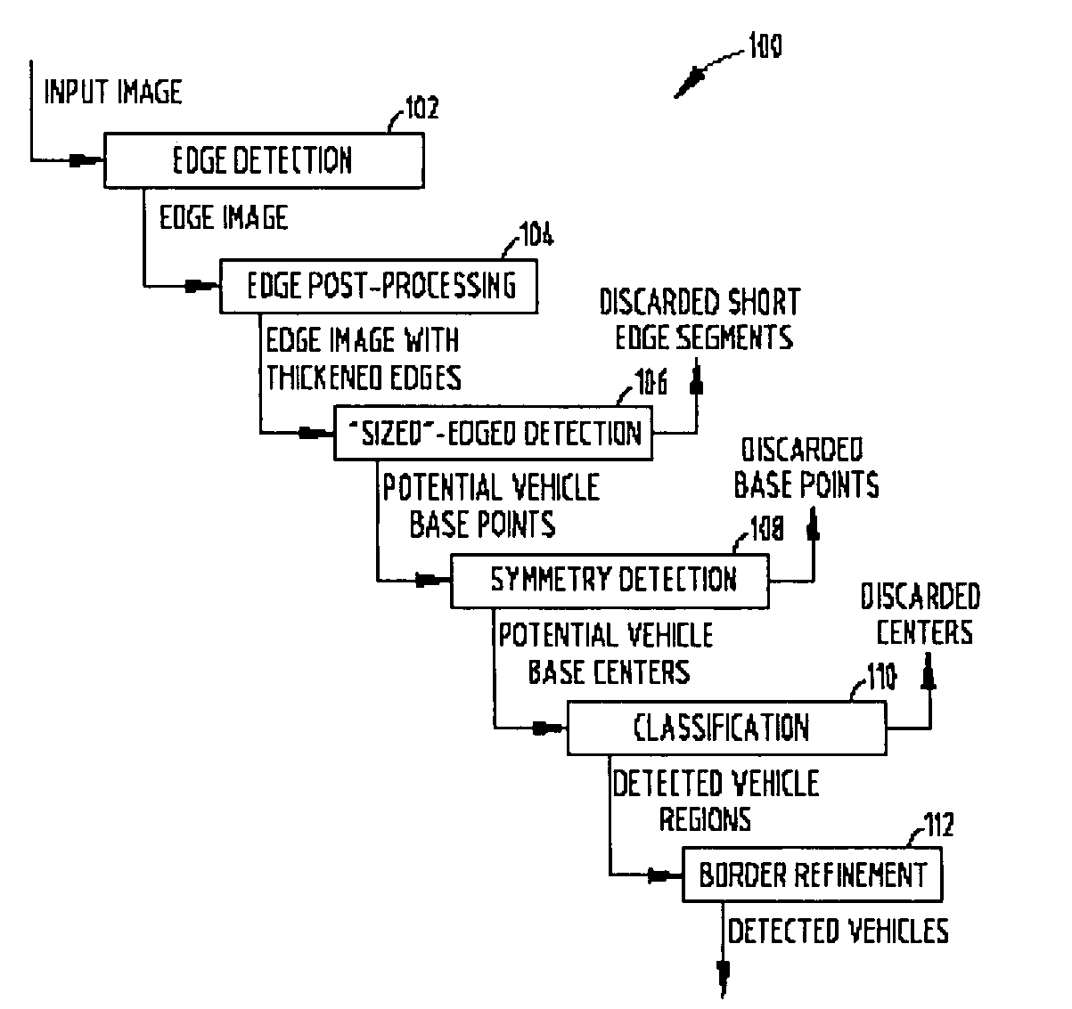
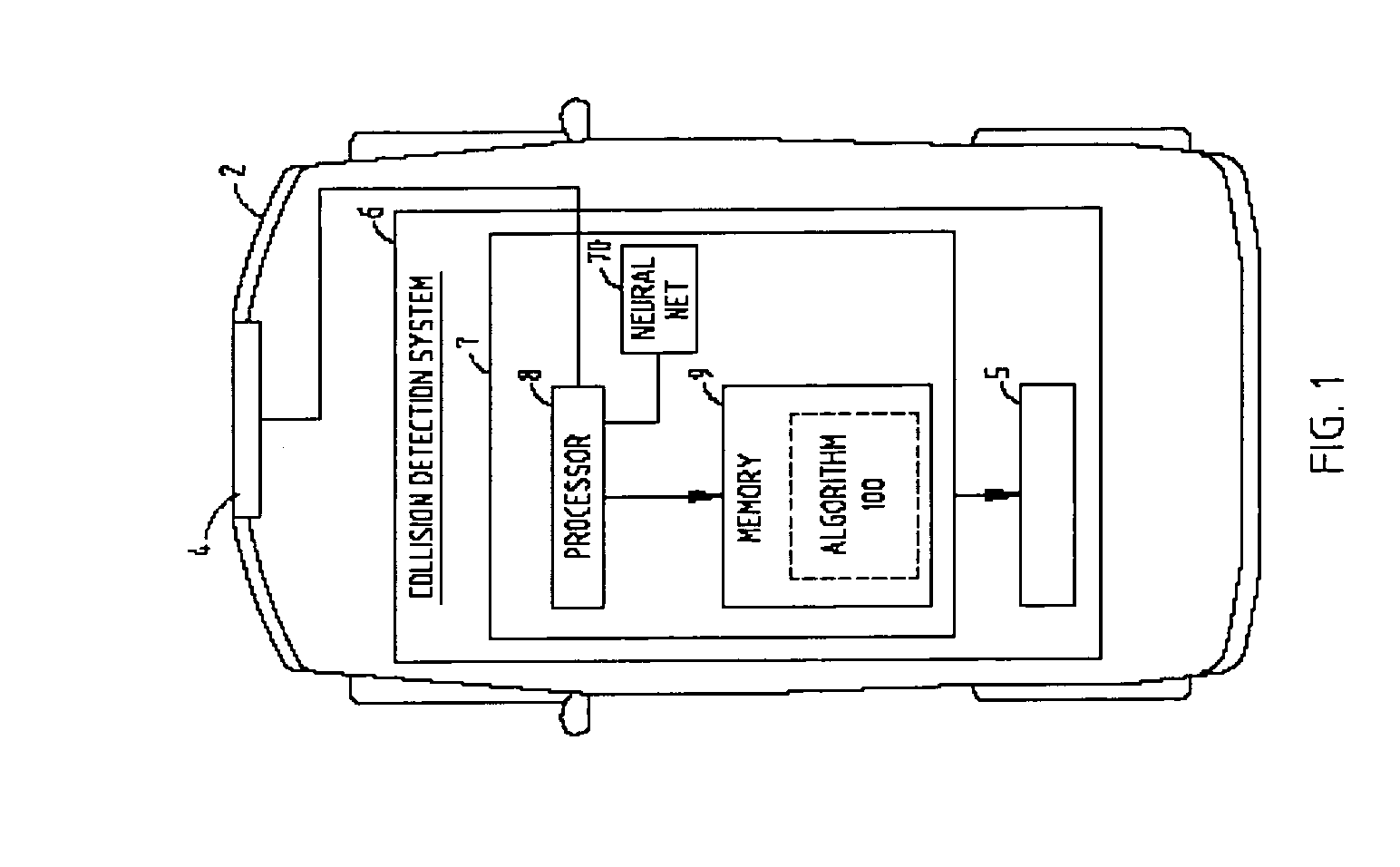
[0028]FIG. 1 generally illustrates a vehicle 2 having a camera 4 coupled to a collision detection system 6, according to one embodiment of the present invention. The camera 4 is shown located in a forward location of the vehicle 2, and is configured to provide electronic images of a view to the front of the vehicle 2 to the collision detection system 6. Collision detection system 6 is shown including a detection system 7 configured to identify potential vehicle locations in the images provided to collision detection system 6 by camera 4. Detection system 7 includes a processor 8 coupled to memory 9 and a neural network 70. Memory 9 includes an algorithm, such as, for example, the algorithm 100 (discussed below) that is executed by processor 8 to cause detection system 7 to identify potential vehicle locations in the electronic images provided to collision detection system 6 by camera 4. As shown, detection system 7 is coupled to additional processing circuitry 5. Detection system 7 ...


PUM


Abstract

A method for identifying objects in an electronic image is provided. The method includes the steps of providing an electronic source image and processing the electronic source image to identify edge pixels. The method further includes the steps of providing an electronic representation of the edge pixels and processing the electronic representation of the edge pixels to identify valid edge center pixels. The method still further includes the step of proving an electronic representation of the valid edge center pixels. Each valid edge center pixel represents the approximate center of a horizontal edge segment of a target width. The horizontal edge segment is made up of essentially contiguous edge pixels. The method also includes the steps of determining symmetry values of test regions associated with valid edge center pixels, and classifying the test regions based on factors including symmetry.

Description

TECHNICAL FIELD[0001]The present invention is generally directed to electronic image processing, and more specifically, to a method for identifying the potential location of vehicles in electronic images.BACKGROUND OF THE INVENTION[0002]As the volume and complexity of vehicular traffic has continued to increase worldwide, so has the need for collision warning systems to help vehicle drivers avoid collisions. Examples of collision warning systems include forward collision warning systems, blind spot warning systems, lane departure warning systems, intersection collision warning systems, and pedestrian detection systems. Typically, many of these systems employ radar sensors, or a combination of radar and vision sensors to perform vehicle detection and recognition.[0003]One problem typically associated with a “radar only” approach to vehicle detection is multiple false positives, which is the indication of the presence of a vehicle in an area when no vehicle is actually present in that...

Claims


Application Information

Patent Timeline
Patent Type & Authority Patents(United States)
IPC IPC(8): G06K9/00
CPCG06K9/3241G06K9/00805G06T7/004B60W30/08G08G1/16G06K2209/23G08G1/166G06T7/70G06V20/58G06V10/255G06V2201/08
Inventor DHUA, ARNAB S.ZHANG, YANKISELEWICH, STEPHEN J.
Owner APTIV TECH LTD
Why Eureka
Try Eureka