Method and device for sensing wear

a technology of wear and sensing, applied in the direction of abrasion/wear resistance investigation, instruments, material analysis, etc., can solve the problems of crushing, cracking, breaking or otherwise forming into smaller parts, and wear on the inside of the mill is a serious problem, and it is difficult to predict accurately the best time to replace the liners

Inactive Publication Date: 2010-03-16
MCGILL UNIV
View PDF22 Cites 39 Cited by
  • Summary
  • Abstract
  • Description
  • Claims
  • Application Information

AI Technical Summary

Problems solved by technology

The impact causes the ore to be crushed, cracked, broken or otherwise formed into smaller particulates.
In view of the abrasive character of the material being ground, the wear on the inside of the mill is a serious problem.
As a result, it is difficult to predict accurately the best time to replace the liners.
Indeed, one problem with prior art mills is that in order to assess the current state of wear of the liners, the mill must be stopped, cleaned and a physical examination of the liners take place.
As commercial scale mills are quite large, and process many tons of ore per hour, regularly halting the process and cleaning the mill to determine the state of wear of the liners is impractical.
Additionally, in cases of excessive liner wear, increasingly the abrasive particulate matter forms a slurry which races down the inside of the mill shell.
Such slurry racing leads to greater abrasive forces being brought to bear on the inside of the mill shell, which can quickly lead to major damage of the mill shell.

Method used


Image

  • Method and device for sensing wear
  • Method and device for sensing wear
  • Method and device for sensing wear

Examples


Embodiment Construction

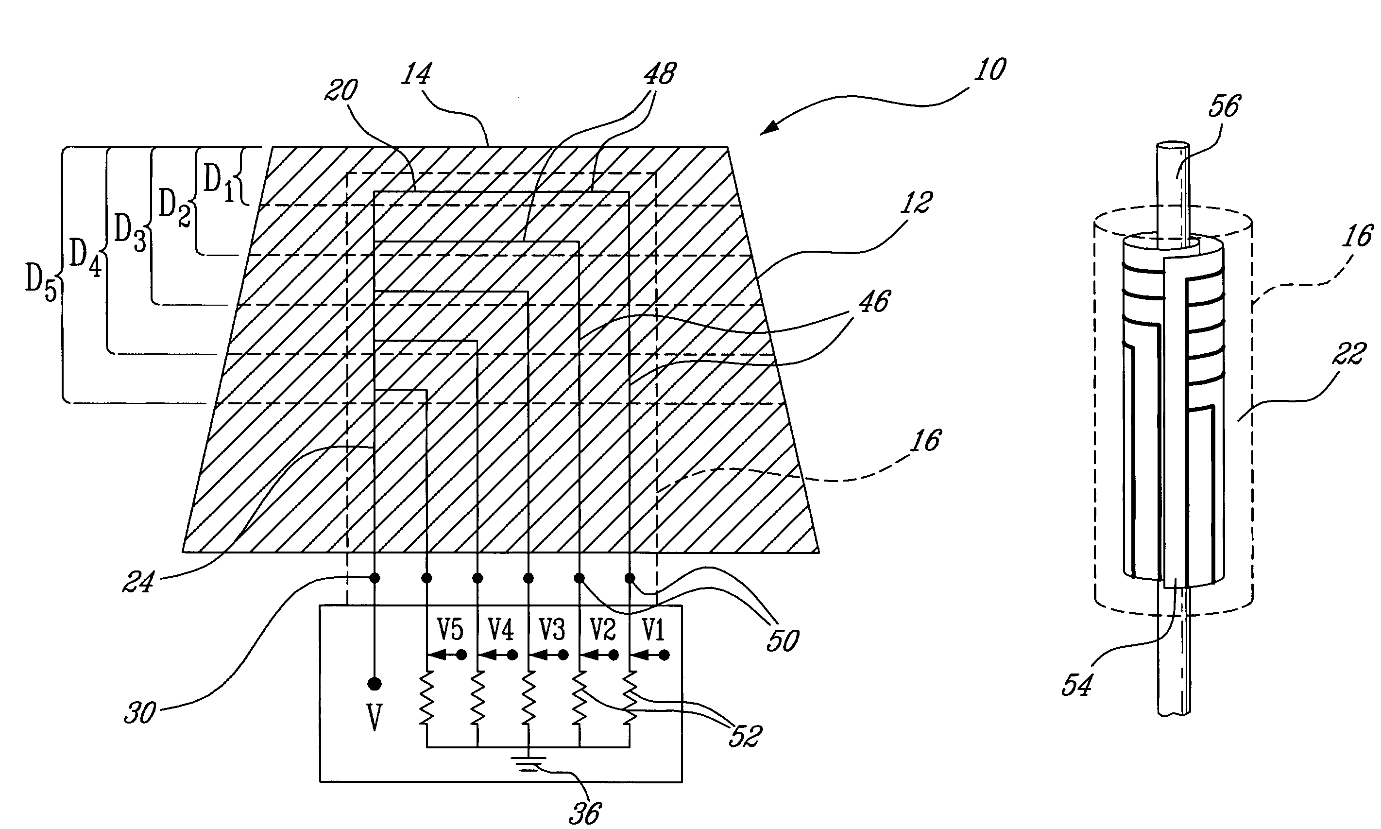
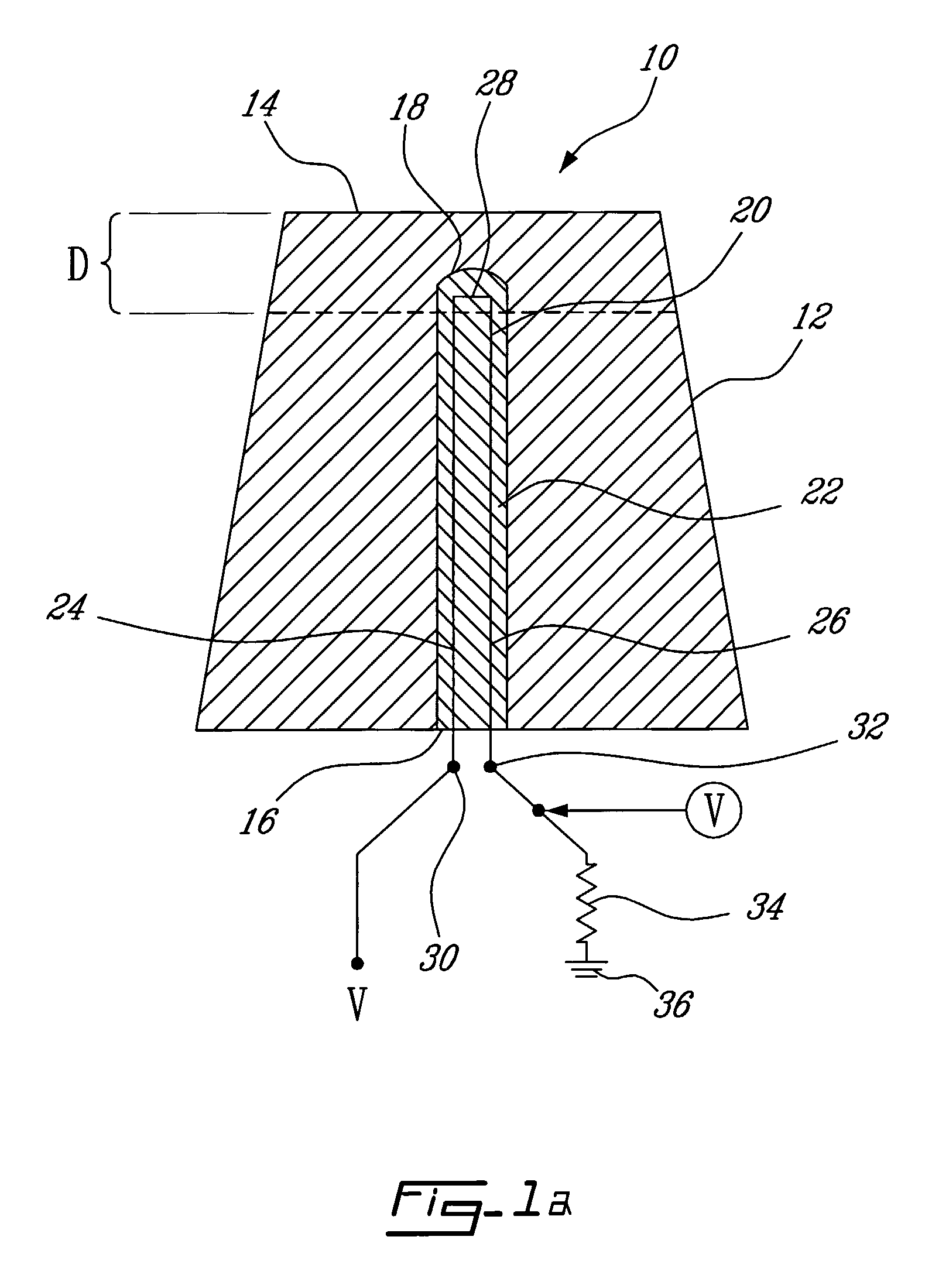
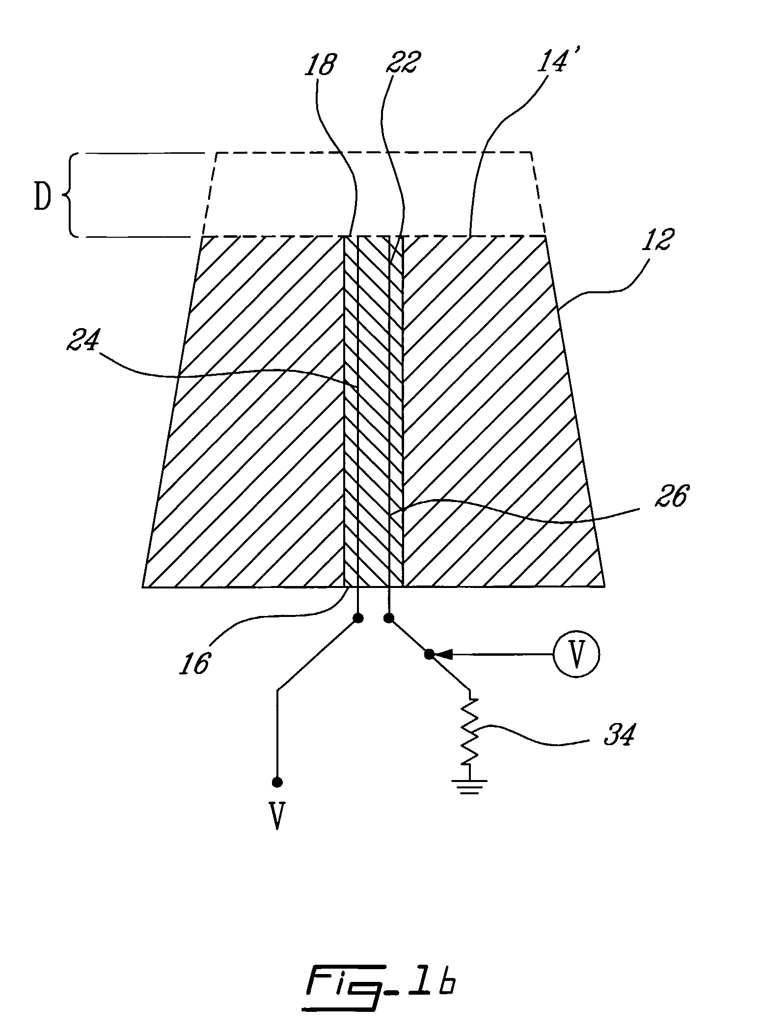
[0022]Referring to FIG. 1A, an illustrative embodiment of a wear sensor in accordance with an illustrative embodiment of the present invention. The wear sensor, generally referred to using the reference numeral 10, is comprised of a component 12 in which wear is to be sensed. The component has at least one wear surface 14 which will be slowly eroded through, for example, contact with abrasive articles or the like (not shown). A cavity 16 is machined or otherwise shaped into the component 12 with the tip 18 of the cavity 16 being positioned in proximity to the wear surface 14. A signal carrying loop 20 is inserted into the cavity 16 and secured therein using a filler material (or matrix) 22. The filler material 22, for example, is a non-conductive self hardening compound such as epoxy resin or the like.

[0023]In an alternative embodiment, the loop 20 could be directly moulded into the component 12 during fabrication, or comprise a lamination applied to the component 12.

[0024]Still ref...


PUM

PropertyMeasurementUnit
diametersaaaaaaaaaa
erosionaaaaaaaaaa
distanceaaaaaaaaaa

Abstract

A sensor for detecting erosion of a wear surface of a component, particularly a liner attached to the mill shell of a rotating grinding mill. The sensor comprises a conductive element embedded in the component, the conductive element comprising a first end positioned at a first distance from the wear surface, at least one conductive loop comprising a wear portion positioned at a second distance from the wear surface proximate to the first end and a circuit coupled to the at least one element for determining a continuity of the conductive loop.

Description

[0001]The present invention claims the benefit of a commonly assigned provisional application entitled “Wear Sensor”, which was filed on Feb. 27, 2004 and assigned the Ser. No. 60 / 547,768. The entire contents of the foregoing provisional patent application are hereby incorporated by reference.FIELD OF THE INVENTION[0002]The present invention relates to a method and device for sensing wear. In particular, the present invention relates to a wear sensor for sensing the erosion of a wear surface of a component.BACKGROUND TO THE INVENTION[0003]Ores that are mined from the ground are obtained in a wide variety of sizes of particulates, varying from relatively small sizes to large chunks of mineralized material. The ore must be reduced to a size of particulate into a fine sieve range that is suitable for flotation where, through the use of suitable additives, the ore bearing particles are separated from the gangue.[0004]One technique used by the mining industry to affect the requisite redu...

Claims


Application Information

Patent Timeline
Patent Type & Authority Patents(United States)
IPC IPC(8): G01N3/56B02C23/00G01N17/00G01N27/20
CPCG01N3/56B02C2210/01
Inventor RADZISZEWSKI, PETERMARTINS, SUDARSHANBENSON, COLEMAN
Owner MCGILL UNIV
Why Eureka
Try Eureka