Self-boring and self-tapping screw

a self-boring, screw technology, applied in the direction of threaded fasteners, screws, fastening means, etc., can solve the problems of high friction of thread-free shaft sections, disadvantageous high driving torque, and difficulty in rolling process screw manufacture, etc., to achieve simple and rapid manufacture, reduce friction and driving torque, and improve the effect of screw production

Active Publication Date: 2010-03-16
SPAX INT
View PDF16 Cites 34 Cited by
  • Summary
  • Abstract
  • Description
  • Claims
  • Application Information

AI Technical Summary

Benefits of technology

[0008]A self-tapping screw according to the present invention includes a shaft having a thread-free section, a threaded section, and a screw tip. A threaded section includes a core section displaced from the screw-tip having a polygonal core cross section. Corners of the core cross-section define an enveloping circle having an enveloping circle diameter larger than a shaft diameter of the thread-free section of the shaft. The polygonal core section and its corners cause the threaded hole to expand during driving of the screw. The result is that the friction and the driving torque are reduced as the thread-free section of the shaft penetrates into the threaded hole. Providing the polygonal core section in the area of the threaded section (and not in the area of the thread-free section of the shaft) results in improved production of the screw by a rolling process. In the rolling process, the screw is clamped between the roller jaws over the thread, including directly on the polygonal section. Thus, bending forces do not act on the axis of the screw. This permits simple and rapid manufacture with high precision in the rolling process.

Problems solved by technology

In practice, the thread-free section of the shaft may generate high friction on entering the threaded hole formed by the threaded section.
This leads to a disadvantageously high driving torque.
However, manufacture of such screws by a rolling process may be problematic.
This means that a straight screw cannot be easily produced, or can only be produced with additional cost.

Method used


Image

  • Self-boring and self-tapping screw
  • Self-boring and self-tapping screw
  • Self-boring and self-tapping screw

Examples


Embodiment Construction

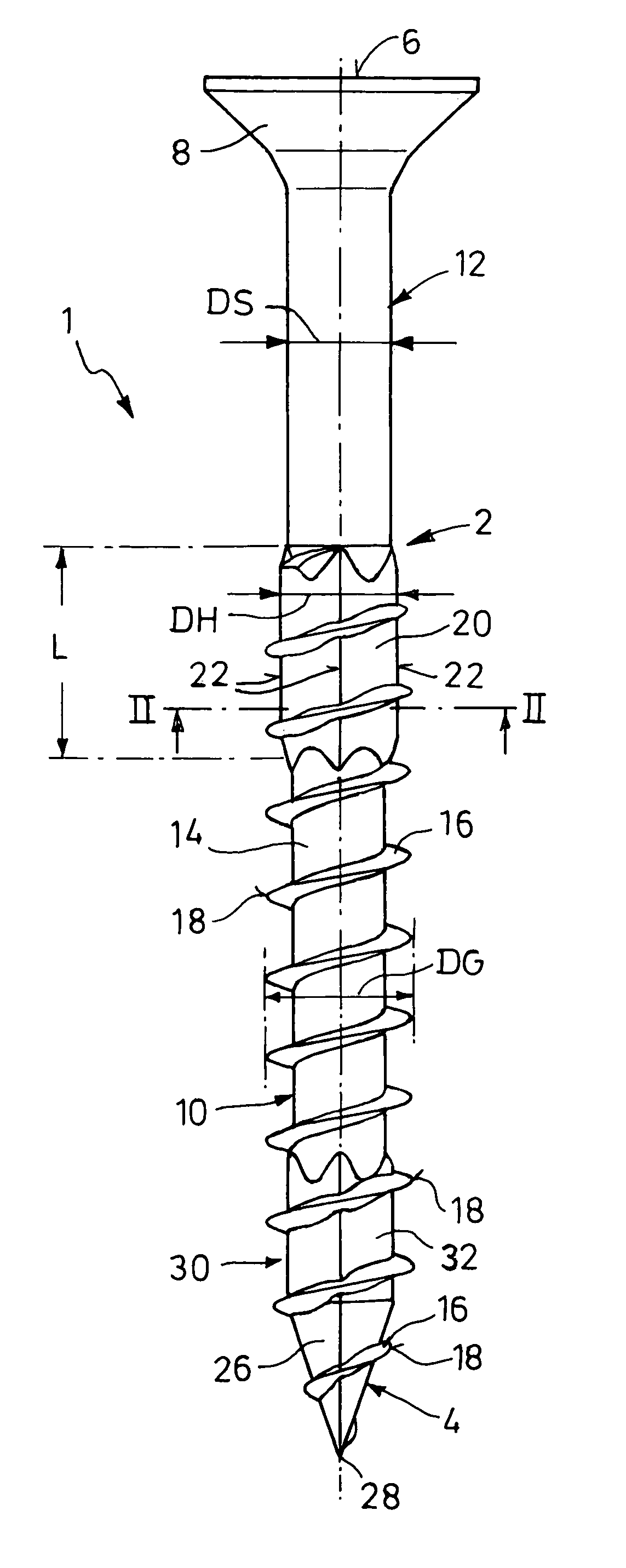
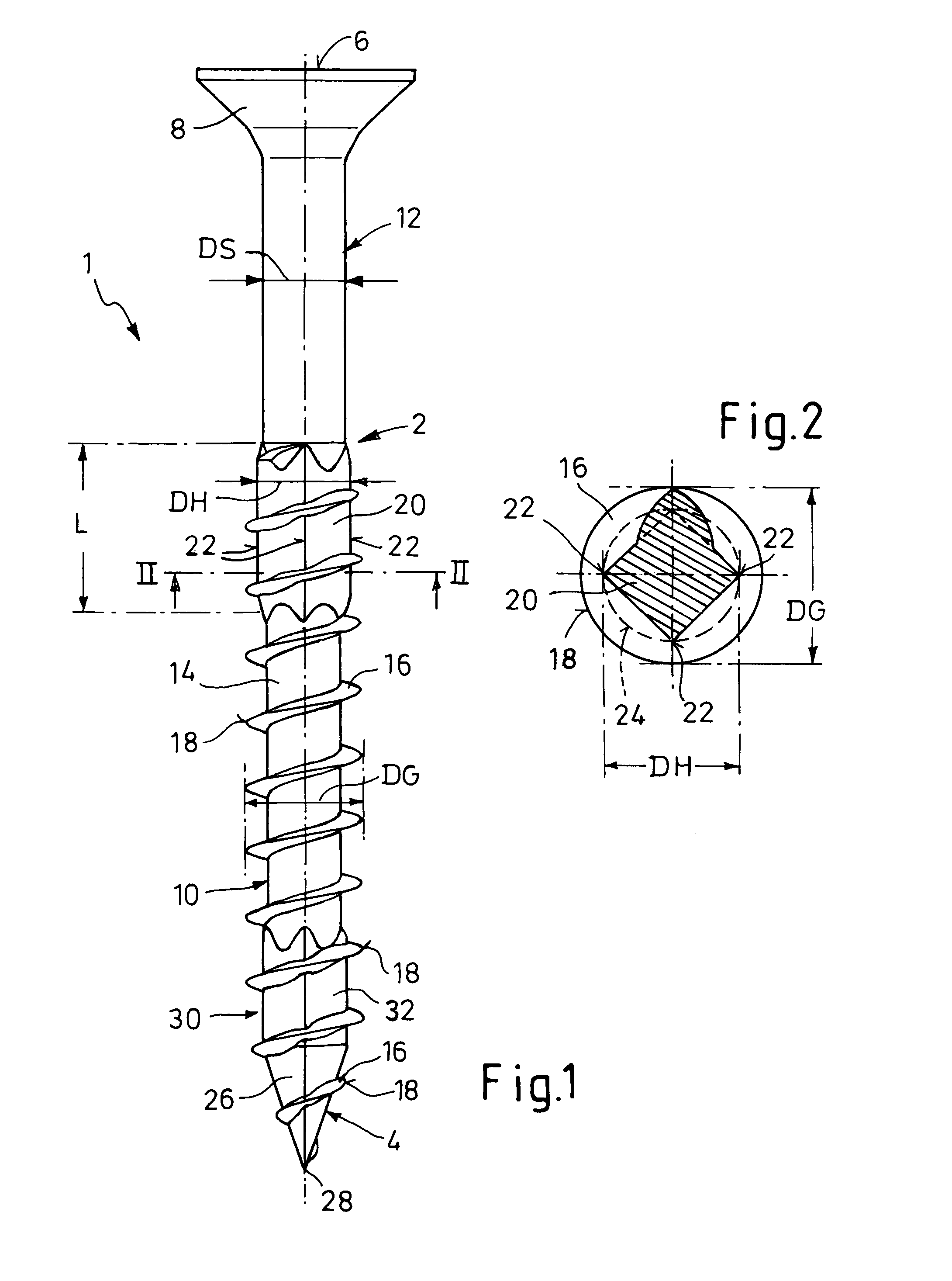
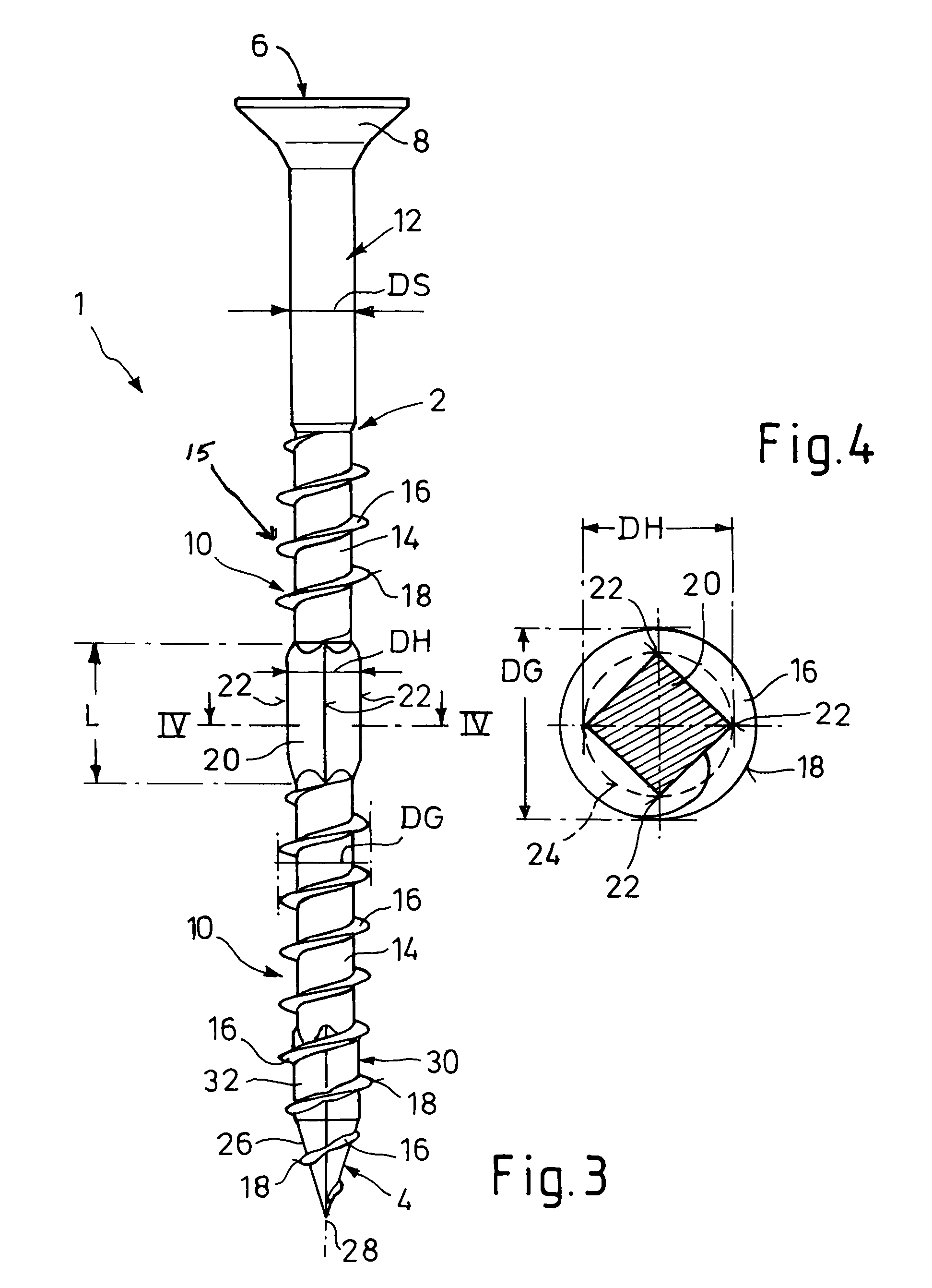
[0015]Turning to FIG. 1, a screw 1 according to the present invention includes a long and narrow screw shaft 2 extending from a screw tip 4 at one end to a screw head 8 at the other end. The screw head 8 further includes a force application member 6 for the transmission of a turning torque. In the depicted embodiments, the force application member 6 is embodied as an internal point of application of a force and as such is not shown in the side views. In addition, the force application member 6 is formed on or in the screw head 8, which is formed as a countersunk head. The force application member 6 can be formed as a cross-head, an internal hexagonal socket head, a hexalobular internal driving button head (TORX) or the like. It can also be an external point of application of a force, for example an external hexagonal socket head.

[0016]The screw shaft 2 includes a threaded section 10 also including the screw tip 4. A thread-free section of the shaft 12, having the force application m...


PUM

PropertyMeasurementUnit
circle diameter DHaaaaaaaaaa

Abstract

The invention relates to a self-boring and thread-forming tapping screw having a screw shaft with a screw tip at one end and at the other end a force application member for the transmission of a turning moment. The screw shaft includes a threaded section with the screw tip and an adjacent thread-free section of the shaft including the force application member. The threaded section has a shaft core and a self-tapping thread. The threaded section includes a core section axially displaced from the tip and having a polygonal core cross section. Corners of the core cross section define an enveloping circle with an enveloping circle diameter larger than a shaft diameter of the thread-free section.

Description

CROSS REFERENCE TO RELATED APPLICATIONS[0001]This application claims priority to German utility model number 20 2006 000 479.3, filed Jan. 12, 2006.BACKGROUND[0002]1. Field of the Invention[0003]The present invention relates to a fastener. More specifically, the invention relates to a self-boring and self-tapping screw.[0004]2. Description of Related Art[0005]A shaft of screws of the above referenced kind include a thread-free section and are also designated as partially-threaded screws. They can be screwed directly without pre-drilling into relatively soft materials, such as wood and the like. In practice, the thread-free section of the shaft may generate high friction on entering the threaded hole formed by the threaded section. This leads to a disadvantageously high driving torque.[0006]Some existing partially-threaded screws of this kind include a shaft cutter adjacent to the thread-free section of the shaft adjacent to the threaded section. The shaft cutter includes radially pr...

Claims


Application Information

Patent Timeline
Patent Type & Authority Patents(United States)
IPC IPC(8): F16B25/00
CPCF16B25/00F16B35/041F16B25/0078F16B25/0015
Inventor LANGEWIESCHE, FRANK
Owner SPAX INT
Why Eureka
Try Eureka