Tiller arm

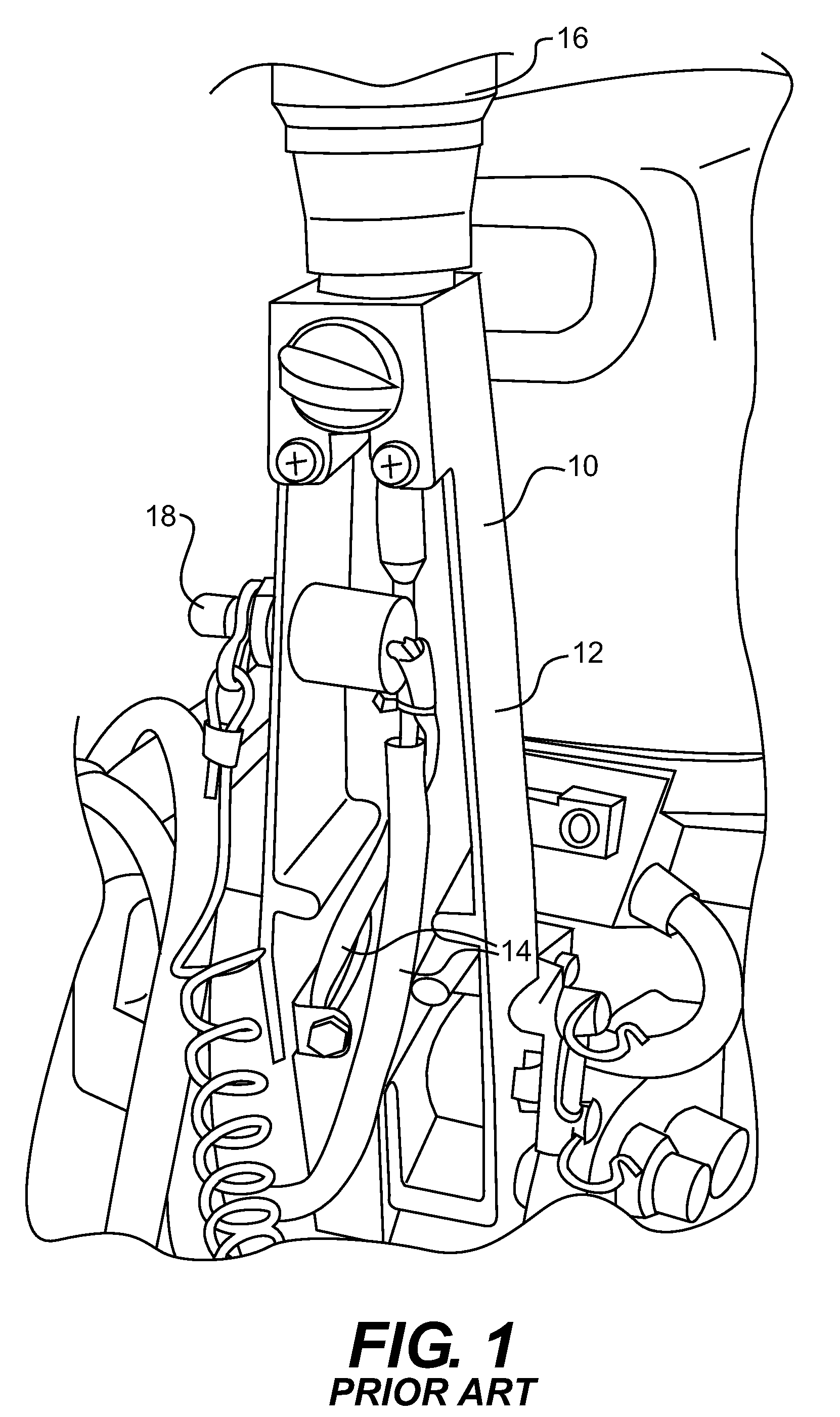
a technology of tiller arms and tillers, which is applied in the field of tiller arms, can solve the problems of affecting the grip of the user's hands, affecting the performance of the watercraft to which the outboard engine is mounted, and cumbersome transportation of the outboard engine,

Inactive Publication Date: 2010-03-16
BRP US
View PDF2 Cites 23 Cited by
  • Summary
  • Abstract
  • Description
  • Claims
  • Application Information

AI Technical Summary

Problems solved by technology

While conventional tiller arms are generally adequate for operating outboard engines, they have a number of drawbacks.
As a result, bulk and weight are added to an already large engine, resulting in diminished performance of the watercraft to which the outboard engine is mounted, and making transportation of the outboard engine cumbersome.
A larger tiller arm may also be difficult for a user to grip with his hands, adding to the difficulty in transporting the outboard engine.
In addition, large tiller arms are costly to manufacture, due to their increased size and the increased quantity of aluminum and other materials required.
Adding or removing even minor features of a cast aluminum tiller arm, for example to make ergonomic modifications or add or remove controls, may require replacing the mold used in the casting process, which represents a significant additional expense and discourages improvements to existing designs.
In addition, some users consider a large and bulky tiller arm to be aesthetically displeasing.
However, such large and bulky tiller arms may be required to physically steer an engine that is large enough to satisfy the user's power requirements but still small enough to be used on a watercraft without separate steering and engine controls.
However, due to the lower structural rigidity of plastic compared to aluminum, plastic tiller arms are currently used only on the smallest of outboard engines, typically those below 10 horsepower.

Method used


Image

  • Tiller arm
  • Tiller arm
  • Tiller arm

Examples


Embodiment Construction

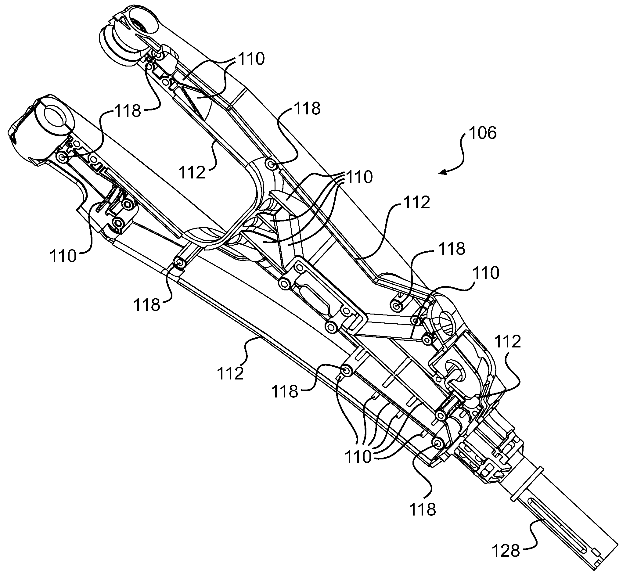
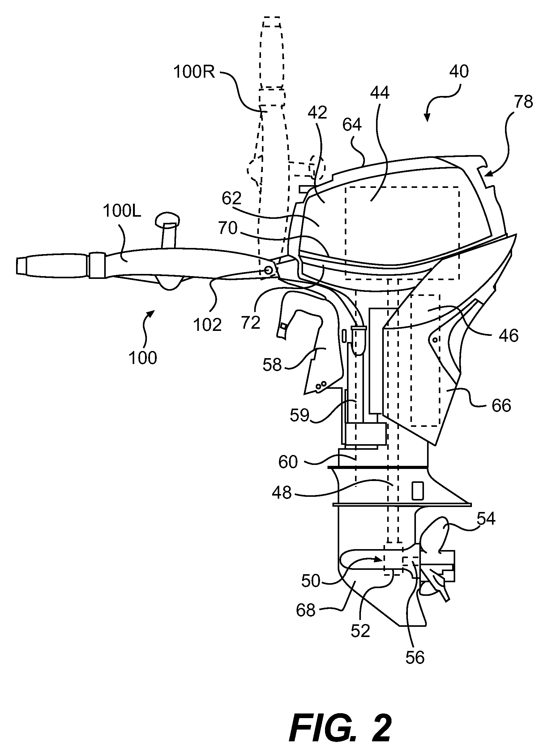
[0048]Referring to FIG. 2, an outboard engine 40 will be described having a tiller arm 100 according to an embodiment of the invention.

[0049]FIG. 2 is a side view of a marine outboard engine 40 having a cowling 42. The cowling 42 surrounds and protects an engine 44, shown schematically. The engine 44 may be any suitable engine known in the art, such as an internal combustion engine. An exhaust system 46, shown schematically, is connected to the engine 44 and is also surrounded by the cowling 42.

[0050]The engine 44 is coupled to a vertically oriented driveshaft 48. The driveshaft 48 is coupled to a drive mechanism 50, which includes a transmission 52 and a bladed rotor, such as a propeller assembly 54 mounted on a propeller shaft 56. The propeller shaft 56 is generally perpendicular to the driveshaft 48. Other known components of an engine assembly are included within the cowling 42, such as a starter motor and an alternator. As it is believed that these components would be readily r...


PUM


Abstract

A tiller arm pivotably mountable to a marine outboard engine about a pivot axis is described. First and second arms extend away from the pivot axis. A middle portion has a first end attached to the first and second arms. A handle portion extends away from the second end of the middle portion in a direction away from the pivot axis. A throttle grip is rotatably mounted to the handle portion and rotatable with respect thereto about a throttle grip axis generally perpendicular to the pivot axis. The throttle grip is operatively connectable to the marine outboard engine. The width of an aperture defined by the arms and the middle section is greater than the widths of the throttle grip and the first and second arms.

Description

CROSS-REFERENCE[0001]The present application is a continuation-in-part of pending U.S. patent application Ser. No. 11 / 848,770 filed on Aug. 31, 2007, the entirety of which is incorporated herein by reference.FIELD OF THE INVENTION[0002]The present invention relates to tiller arms for marine outboard engines.BACKGROUND OF THE INVENTION[0003]Many boats and other watercraft are propelled by one or more outboard engines disposed at the rear of the watercraft, which drive one or more propellers. Many different sizes of outboard engines are available, ranging from below 1 horsepower to over 350 horsepower, depending on the size of the watercraft to be powered and the power requirements of the user. During operation, a number of aspects of the operation of the outboard engine may be controlled by the user, depending on the particular outboard engine, such as starting and stopping the engine; throttle; tilt; trim; steering; shifting between forward, neutral and reverse modes; and the pitch ...

Claims


Application Information

Patent Timeline
Patent Type & Authority Patents(United States)
IPC IPC(8): B63H5/125
CPCB63H20/12B63H21/213
Inventor WIATROWSKI, DARRELLLUCIER, PETERVIGNAU, PIERRE
Owner BRP US
Why Eureka
Try Eureka