
Frame mapping scheduler for scheduling data blocks using a mapping table and a weight table

a data block and frame mapping technology, applied in the field of telecommunications, can solve the problems of long burst periods, unsatisfactory telecommunication system, and very burst service received by usub>1/sub>,

Inactive Publication Date: 2010-03-16
INTEL CORP
View PDF20 Cites 2 Cited by
  • Summary
  • Abstract
  • Description
  • Claims
  • Application Information

AI Technical Summary

Benefits of technology

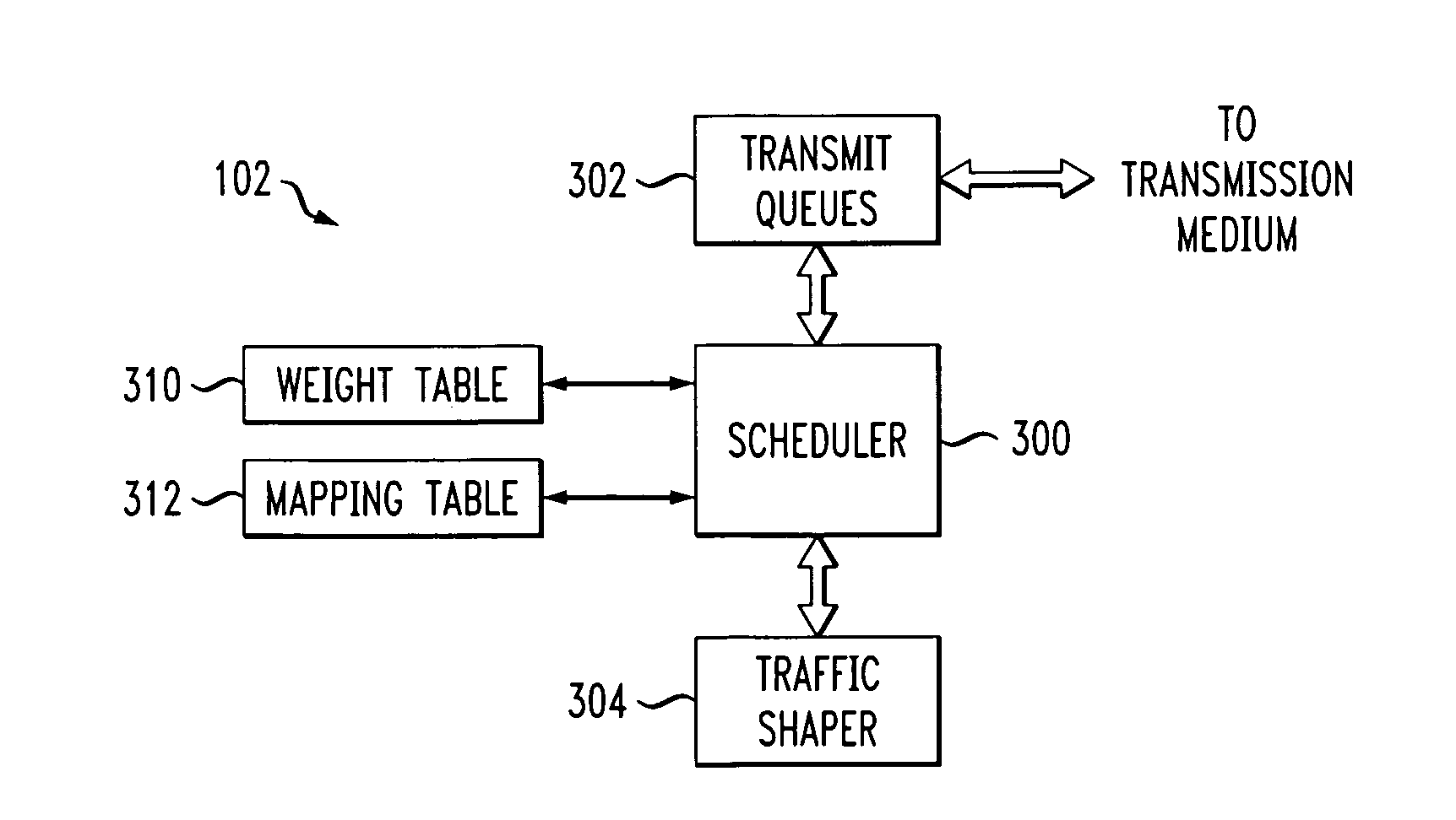
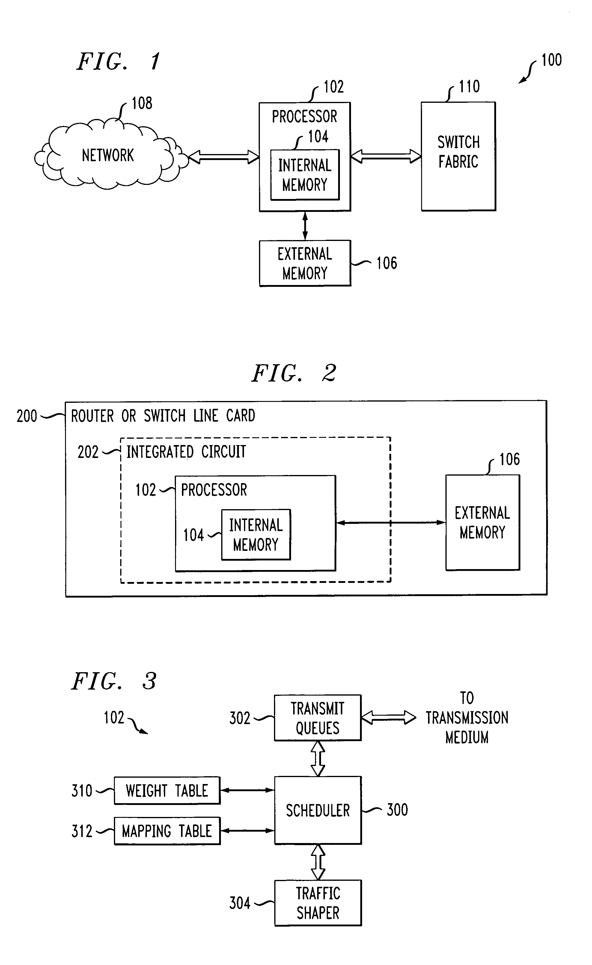
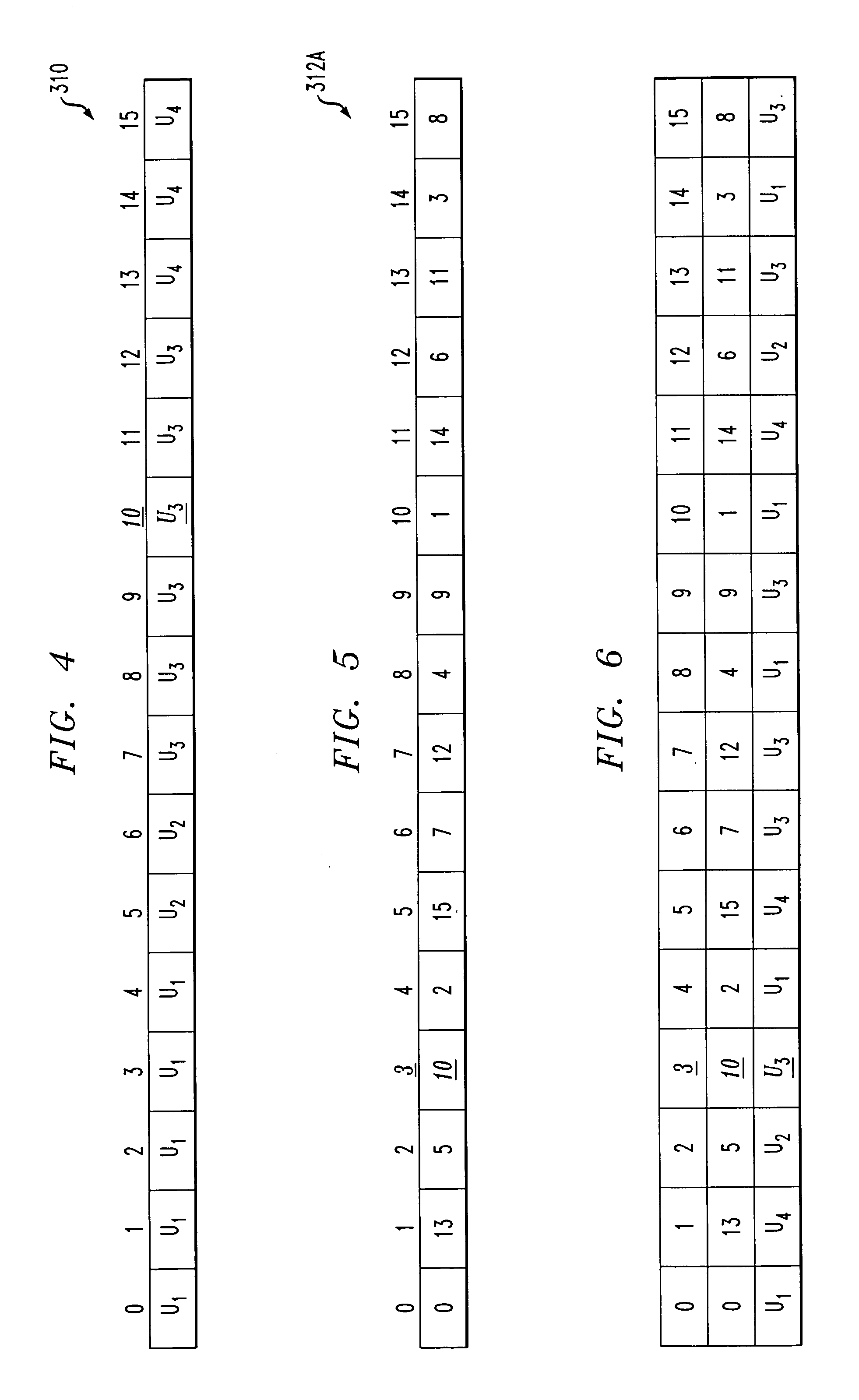
The present invention provides a frame mapping scheduler that simplifies and makes fairer than WRR, but with less burstiness. The scheduler uses a weight table and a mapping table to determine which data blocks should be transmitted in a network processor or other processing device. The weight table contains a list of transmission elements, while the mapping table contains a mapping between timeslots in the frame and the weight table entries. The scheduler accesses the weight table and mapping table to determine which transmission element to schedule in a given timeslot. The weight table entries can be determined based on a golden ratio policy or other policies, and the mapping table entries can be generated based on a bit-reverse policy. The technical effect of the invention is to simplify and make fairer the process of transmitting data blocks in a network processor or other processing device.

Problems solved by technology

A problem with WRR is that it may cause long periods of burstiness.
The service received by U1 is very bursty.
This is clearly not desirable in telecommunication systems, because long burstiness could overflow the buffers of user communication devices.
Such burstiness becomes increasingly problematic in those practical applications in which the total number of users may be several hundreds or more.
Unfortunately, these alternative algorithms are typically considerably more complex than WRR, and therefore may be difficult to implement in network processors and other processing devices operating in high data rate environments.

Method used


Image

  • Frame mapping scheduler for scheduling data blocks using a mapping table and a weight table
  • Frame mapping scheduler for scheduling data blocks using a mapping table and a weight table
  • Frame mapping scheduler for scheduling data blocks using a mapping table and a weight table

Examples


Embodiment Construction

[0024]The invention will be illustrated herein in conjunction with an exemplary system for processing data for transmission through a network. The exemplary system includes a network processor configured in a particular manner in order to illustrate the techniques of the invention. It should be understood, however, that the invention is more generally applicable to any communication system scheduler in which it is desired to provide improved scheduling without the burstiness problem associated with conventional WRR scheduling.

[0025]A “processor” as the term is used herein may be implemented, by way of example and without limitation, utilizing elements such as those commonly associated with a microprocessor, central processing unit (CPU), digital signal processor (DSP), application-specific integrated circuit (ASIC), or other type of data processing device, as well as portions and combinations of such elements.

[0026]The present invention in an illustrative embodiment improves schedul...


PUM


Abstract

A network processor or other processing device of a communication system includes scheduling circuitry configured to schedule data blocks for transmission from a plurality of users or other transmission elements in timeslots of a frame. The scheduling circuitry utilizes a weight table and a mapping table. The weight table comprises a plurality of entries, with each of the entries identifying a particular one of the transmission elements. The mapping table comprises at least one entry specifying a mapping between a particular timeslot of the frame and an entry of the weight table. The scheduling circuitry determines a particular transmission element to be scheduled in a given timeslot by accessing a corresponding mapping table entry and utilizing a resultant value to access the weight table.

Description

FIELD OF THE INVENTION[0001]The present invention relates generally to the field of telecommunications, and more particularly to schedulers used to control access to limited resources.BACKGROUND OF THE INVENTION[0002]In many telecommunications applications, a scheduler is used to resolve contention among multiple tasks competing for a limited resource. For example, such a scheduler is commonly used in a network processor to schedule multiple traffic flows for transmission over a specific transmission bandwidth.[0003]A network processor generally controls the flow of data between a physical transmission medium, such as a physical layer portion of a network, and a switch fabric in a router or other type of switch. An important function of a network processor involves the scheduling of cells, packets or other data blocks, associated with the multiple traffic flows, for transmission to the switch fabric from the physical transmission medium of the network and vice versa. The network pro...

Claims


Application Information

Patent Timeline
Patent Type & Authority Patents(United States)
IPC IPC(8): H04L12/28
CPCH04L41/0896H04L43/026
Inventor LI, JINHUIPOURSEPANJ, ALI A.SIMKINS, MARK BENJAMIN
Owner INTEL CORP
Learn More