Apparatus for processing crop materials in a forage harvester

a technology for crop materials and forage harvesters, applied in mowers, agriculture tools and machines, mowers, etc., can solve the problems of unnecessarily difficult removal and maintenance of rollers, complicating the replacement process, and out of operation of forage harvesters

Active Publication Date: 2010-03-23
SCHERER BOB A
View PDF6 Cites 19 Cited by
  • Summary
  • Abstract
  • Description
  • Claims
  • Application Information

AI Technical Summary

Benefits of technology

[0019]One significant advantage of the present invention is the capability to open the frame and remove the rollers from their mountings on the frame without having to move the rollers through small or restricted openings in the frame, which would make the roller replacement process more difficult and time consuming to perform.

Problems solved by technology

However, the support structures that have also been employed to mount the rollers in the forage harvesters have made the practice of removing and maintaining the rollers unnecessarily difficult, and also the known structures have been thought to have been undersized and insufficiently rugged, causing jamming of the crop material in the roller assembly and breakdowns that take the forage harvester out of operation during harvest time.
This complicates the replacement process and prolongs the amount of time that the roller structure, and thus the crop processing equipment, is taken out of service.
Another significant limitation of known roller assemblies is the narrowing of the path of the crop materials through the assemblies, which can lead to increased incidences of clogging of the roller assembly.
Typically, guides are employed at the lateral sides of the path to move the crop material inward toward the centers of the rollers, but this movement tends to encourage clogging of the path.
Other limitations of the known roller structures are undersized rollers, bearings, greasing systems, and shaft diameters, which also contribute to unnecessary breakdowns of the roller assemblies that can make the crop processing equipment more unreliable than they could be.

Method used


Image

  • Apparatus for processing crop materials in a forage harvester
  • Apparatus for processing crop materials in a forage harvester
  • Apparatus for processing crop materials in a forage harvester

Examples


Embodiment Construction

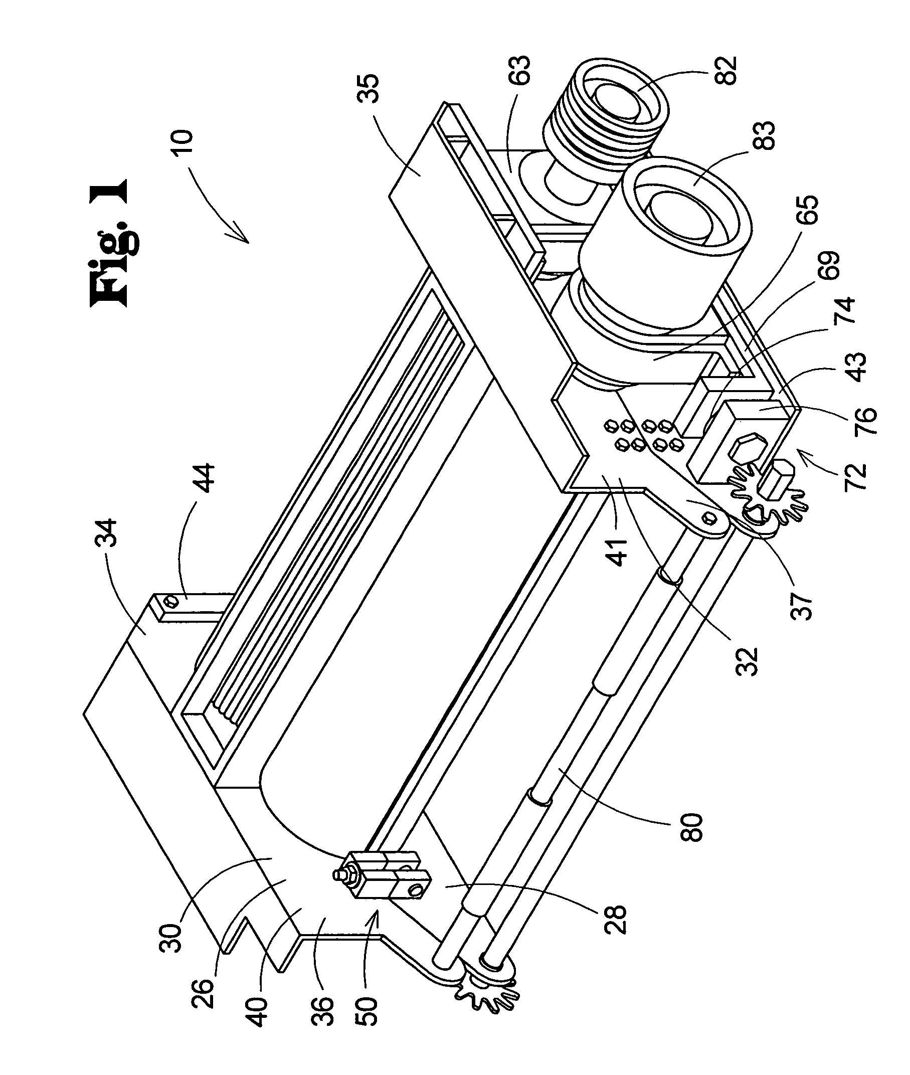
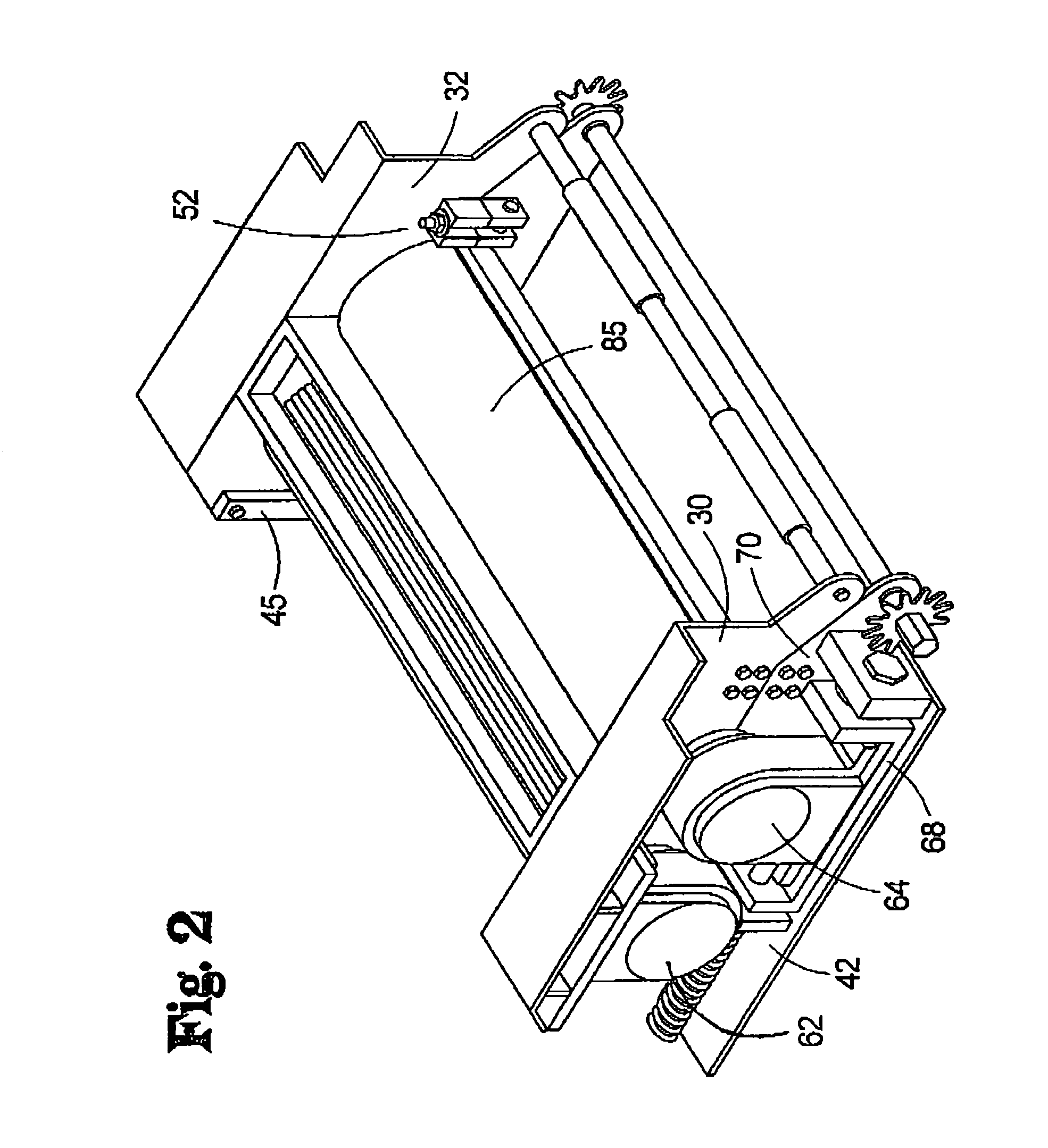
[0026]With reference now to the drawings, and in particular to FIGS. 1 through 4 thereof, a new apparatus embodying the principles and concepts of the present invention and generally designated by the reference numeral 10 will be described.

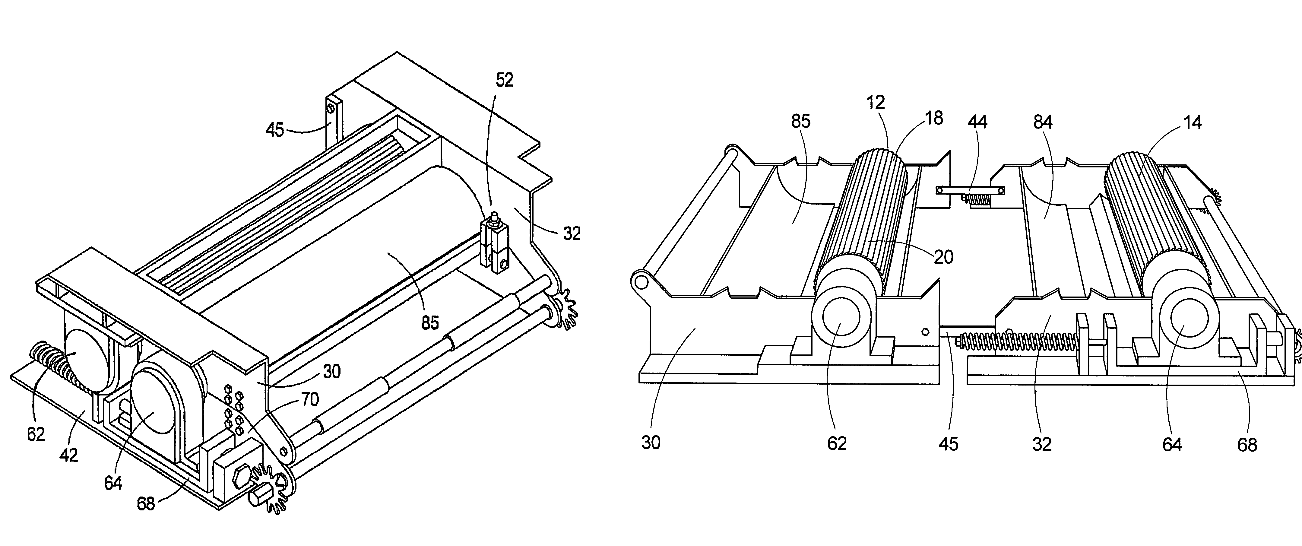
[0027]The invention contemplates an apparatus 10 that is highly suitable for processing crop materials, such as silage, in a forage harvester apparatus, although other applications of the novel concepts of the invention may be implemented. In general, the apparatus 10 includes a pair of rollers 12, 14 for cutting crop materials therebetween, and a frame 24 for supporting the rollers in a proximate condition to each other that permits the rollers 12, 14 to be moved apart from each other to facilitate maintenance of the rollers.

[0028]In greater detail, as shown in FIGS. 3 and 4, each of the pair of rollers 12, 14 may be substantially cylindrical in shape. Each of the rollers 12, 14 may have an exterior that is covered with teeth 16, and each of the ...


PUM


Abstract

An apparatus is disclosed for processing crop materials in a forage harvester. The apparatus may comprise a pair of rotatable rollers for cutting crop materials passed between the rollers, and a bifurcated frame supporting the rollers in a proximate condition to each other. The bifurcated frame includes a first frame portion and a second frame portion, with a first one of the rollers being mounted on the first frame portion for moving with the first portion and a second one of the rollers being mounted on the second frame portion. The first frame portion may be movable with respect to the second frame portion to move the first roller laterally away from the second roller.

Description

REFERENCE TO RELATED APPLICATION[0001]The present utility patent application claims the benefit of the provisional patent application filed in the United States Patent and Trademark Office on Jun. 25, 2003 and assigned the application No. 60 / 482,594.BACKGROUND OF THE INVENTION[0002]1. Field of the Invention[0003]The present invention relates to crop processing equipment and more particularly pertains to a new apparatus for processing crop materials in a forage harvester that has a structure that minimizes the downtime of the forage harvester due to maintenance reasons.[0004]2. Description of the Prior Art[0005]The use of crop processing equipment is known in the prior art. Apparatus such as forage harvesters, such as the Jaguar self-propelled forage harvester available from the Claas of America Corporation of Columbus, Ind., include several stages of the crop material processing for shredding and chopping crop material, such as silage, into a size and condition that is suitable for ...

Claims


Application Information

Patent Timeline
Patent Type & Authority Patents(United States)
IPC IPC(8): A01D61/00A01D82/00
CPCA01D82/00
Inventor SCHERER, BOB A.
Owner SCHERER BOB A
Why Eureka
Try Eureka