Chopping drum for a forage harvester

a technology of forage harvester and drum body, which is applied in the direction of peelers, agriculture tools and machines, cocoa, etc., can solve the problems of affecting the quality of forage harvesting

Active Publication Date: 2012-04-03
DEERE & CO
View PDF5 Cites 12 Cited by
  • Summary
  • Abstract
  • Description
  • Claims
  • Application Information

AI Technical Summary

Benefits of technology

[0008]In this way, the chopping drum is reinforced in the peripheral direction. Simultaneously, the modular construction with screwed blades and blade holders is preserved, which allows simple replacement when necessary.
[0011]The second section angled outward has the advantage that it forms a U-shaped pocket that is suitable, especially in interaction with a leading surface of the first section of the following blade holder inclined forward in the radial direction or relative to the radial in the rotational direction and the inner surface of the chopping blade, as a throw-shovel surface for throwing away the harvested material and offers little or no opportunity for accumulation of the harvested material.

Problems solved by technology

In this way, a relatively high expense for the production of the weld connections is required between the drum body and the blade holders for them to be produced with sufficient accuracy, in order to allow low out-of-balance spinning of the chopping drum and to have to remove as little material as possible from the chopping blades when grinding the chopping blades with a grinding device.
In addition, the weld connections form structural weak points that can be repaired only with difficulty or not at all in the case of wear or damage.
In the case of this prior art, it is considered disadvantageous that the forces are transmitted from the blade holders to the shaft only via the supporting rings, which is why the supporting rings are to be dimensioned with sufficient stability.

Method used


Image

  • Chopping drum for a forage harvester
  • Chopping drum for a forage harvester
  • Chopping drum for a forage harvester

Examples


Embodiment Construction

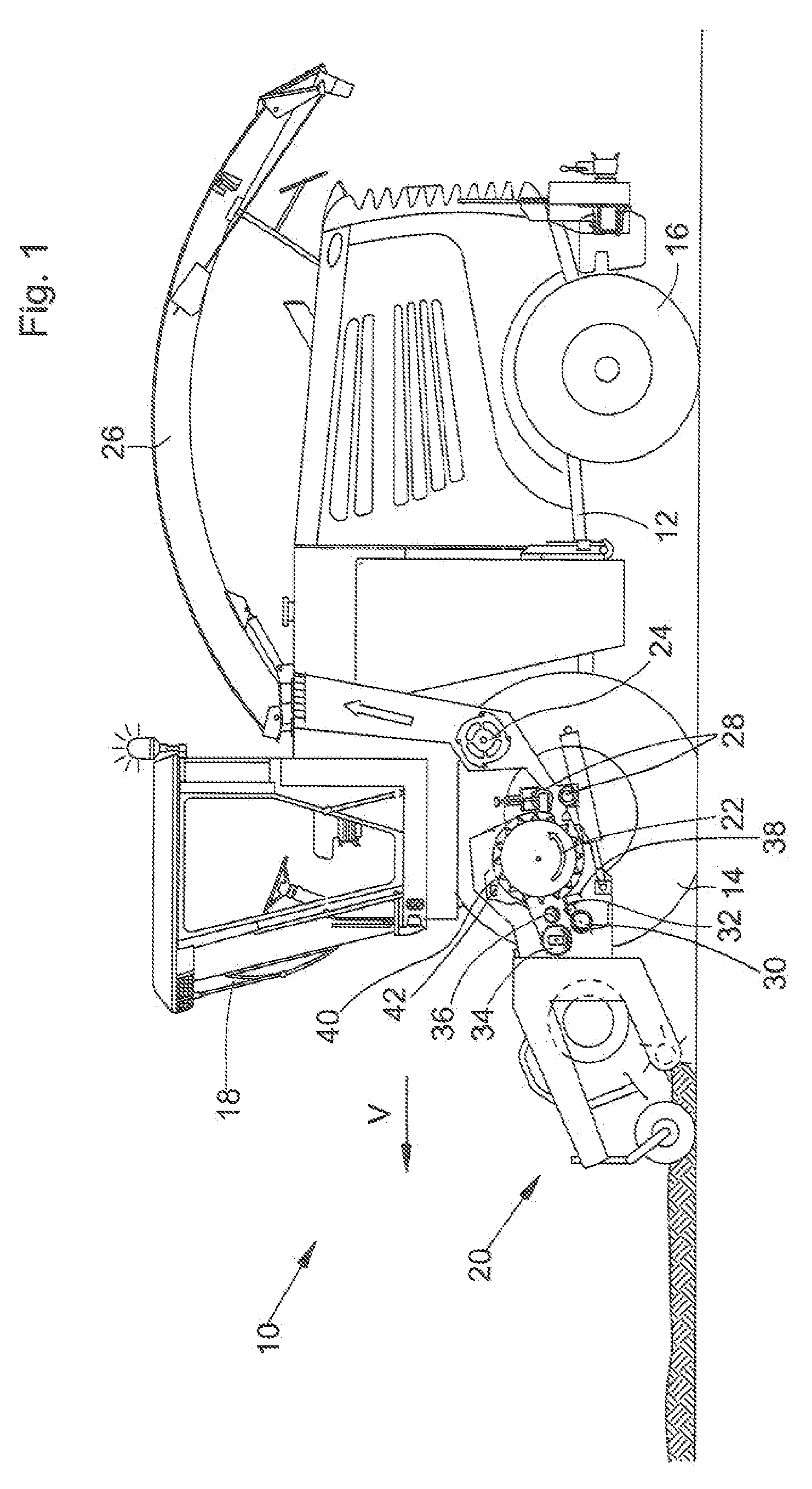
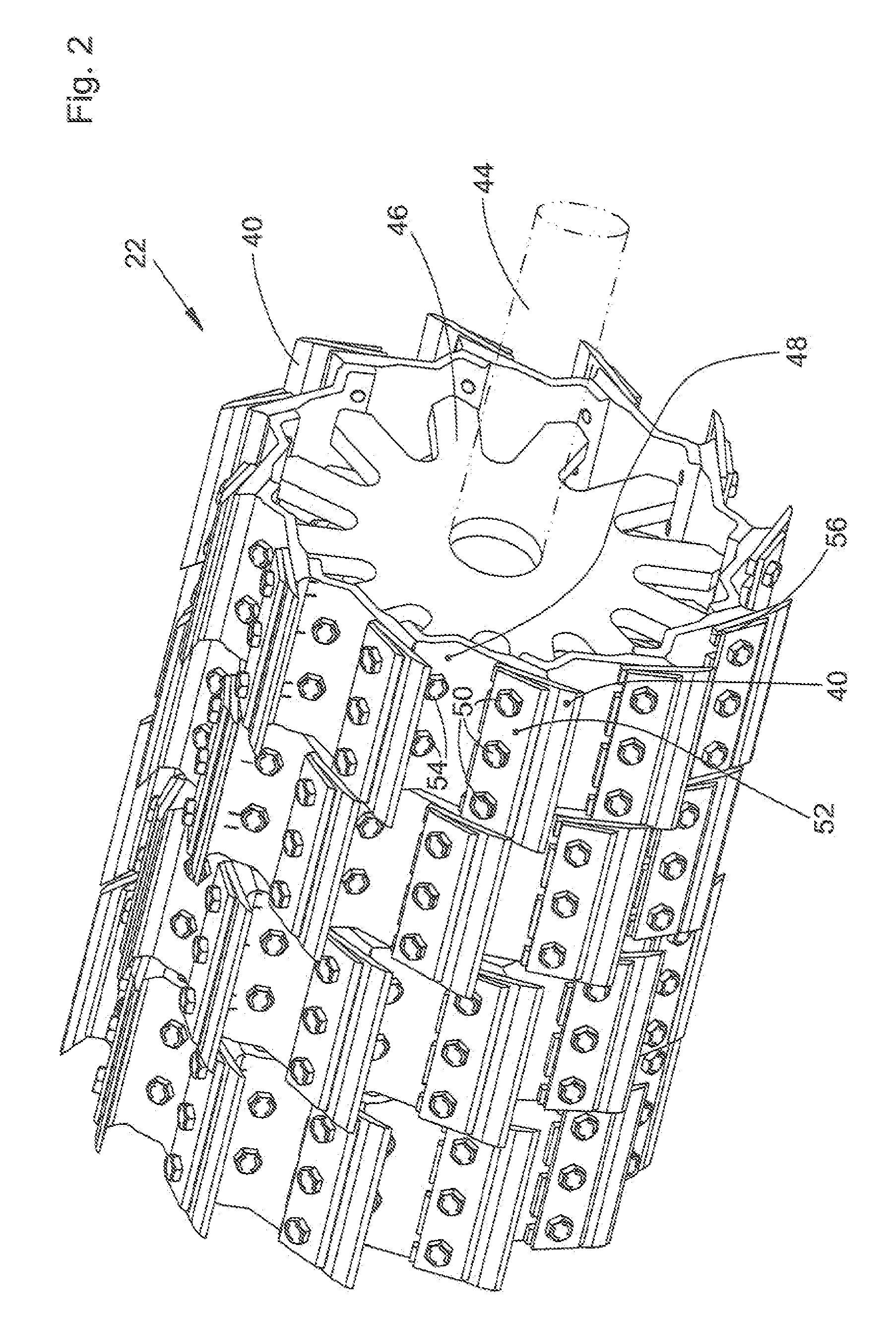
[0015]A self-propelled forage harvester 10 shown in FIG. 1 is mounted on a frame 12 that is supported by front and rear wheels 14 and 16. The operation of the harvesting machine 10 is performed from a driver cabin 18 from which a harvesting material pickup device 20 in the form of a pickup can be seen. Material, e.g., grass or the like, picked up from the ground by means of the harvesting material pickup device 20 is fed to a chopping drum 22 that is provided with chopping blades 40 and chops this material into small pieces in interaction with a counter blade 38 and discharges it to a feeding device 24. The material exits the harvesting machine 10 onto a trailer traveling alongside by means of a discharge chute 26 that can rotate. Between the chopping drum 22 and the feeding device 24, there is a secondary cutting device 28 by which the material to be fed is fed tangentially to the feeding device 24. Between the harvesting material pickup device 20 and the chopping drum 22, the mate...


PUM


Abstract

A chopping drum for a forage harvester has a shaft. Supporting rings are mounted on the shaft one next to the other in the axial direction and extending in the radial direction. Blade holders are distributed around the outer periphery of the supporting rings, and chopping blades are mounted on the blade holders by first screws. The first screws produce a connection between blade holders one following the other in the peripheral direction.

Description

FIELD OF THE INVENTION[0001]The invention relates to a chopping drum for a forage harvester. The chopping drum has a shaft with supporting rings mounted thereon one next to the other in the axial direction and extending in the radial direction. Blade holders are distributed around the outer periphery of the supporting rings, and chopping blades are mounted on the blade holders by first screws.BACKGROUND OF THE INVENTION[0002]Forage harvesters are used for harvesting whole plants or their parts that are taken up, during operation, from a field by means of a harvesting attachment, pressed together by pre-press rollers, and fed to a blade drum whose chopping blades cut up the plants in conjunction with a counter blade. Then the cut-up plants or plant parts are optionally fed to a secondary cutting device and conveyed by a secondary acceleration device into a discharge bend that loads it over onto a transport vehicle. The cut-up plants are typically used as fodder and / or biogas producti...

Claims


Application Information

Patent Timeline
Patent Type & Authority Patents(United States)
IPC IPC(8): B02C18/18
CPCA01F29/095
Inventor BACON, JOSHUA D.
Owner DEERE & CO
Why Eureka
Try Eureka