Feed roll control system for a forage harvester

a control system and forage harvester technology, applied in the field of forage harvesters, can solve the problems of complex system, mechanical springs not ensuring any constant pressure on crops,

a control system and forage harvester technology, applied in the field of forage harvesters, can solve the problems of complex system, mechanical springs not ensuring any constant pressure on crops,

US8056309B2Active Publication Date: 2011-11-15BLUE LEAF I P INC

Image

  • Feed roll control system for a forage harvester
  • Feed roll control system for a forage harvester
  • Feed roll control system for a forage harvester

Examples


Embodiment Construction

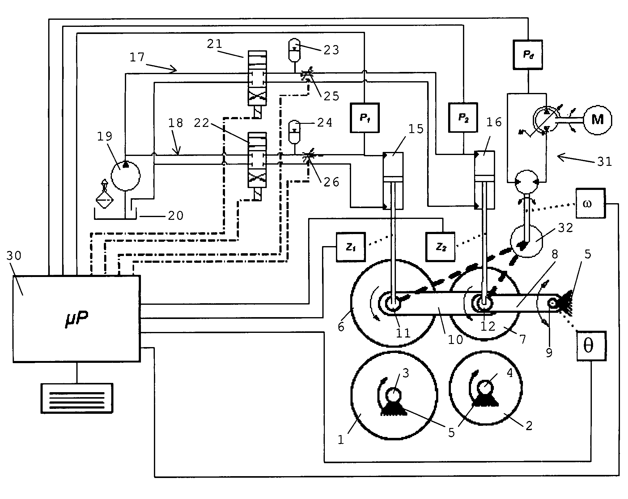
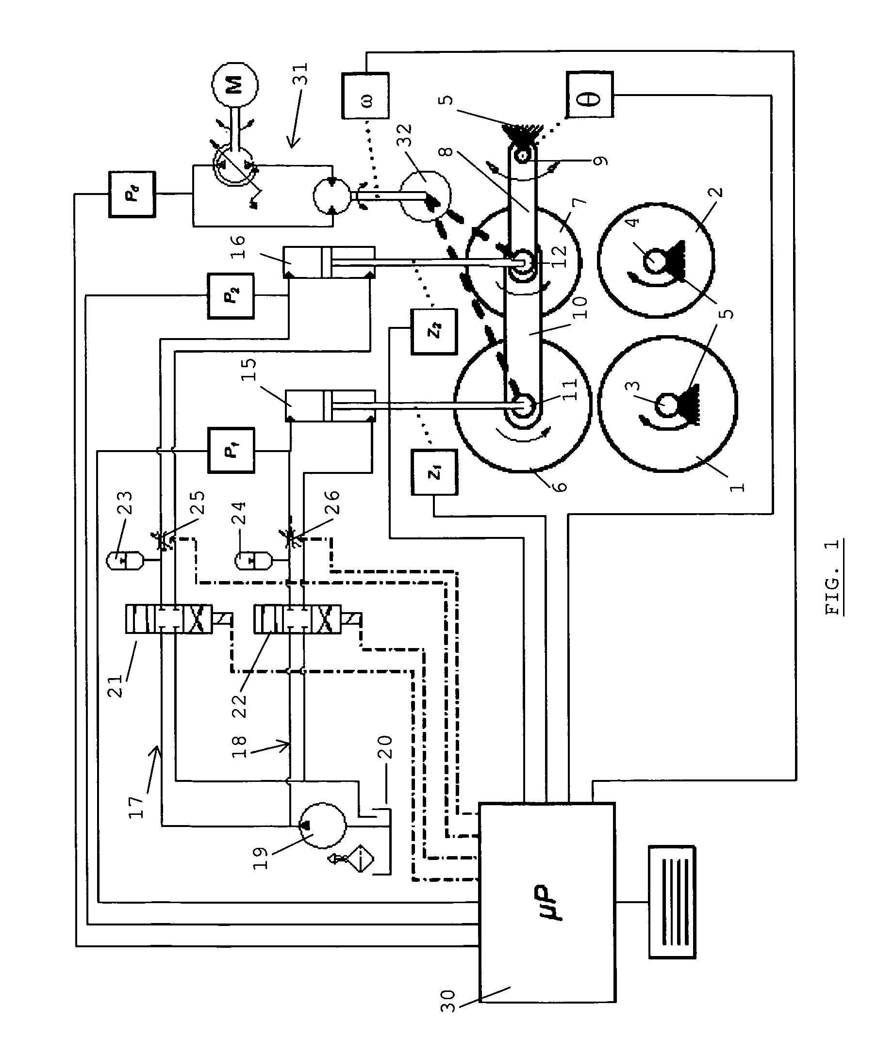
[0010]With reference to FIG. 1, a control system according to the invention is shown schematically, with respect to an exemplary feed roll arrangement installed in a forage harvester, comprising two lower rolls 1 and 2 arranged to rotate around rotation axes of shafts 3 and 4 which are fixed with respect to a main frame or a subframe 5 of the forage harvester, and two movable upper feed rolls 6 and 7, arranged to rotate around movable shafts 11 and 12. This feed roll arrangement is installed in the forage harvester so that harvested crops are fed from left to right on the drawing (i. e. front to back of the machine) through rotation of the feed rolls in the indicated rotation directions. The cutting drum (not shown) and stationary shearbar (not shown) are present to the right of the feed rolls. The feed rolls are powered by an external power source, through a gearbox transmission, as known in the art and not shown in the drawing. Upward and downward movement of the right hand side u...


PUM


Abstract

A system to control the position of one or more feed rolls in a forage harvester. The system includes at least one fixed feed roll arranged to rotate around a rotation axis which is fixed with respect to a chassis of the harvester, and in cooperation with the at least one fixed feed roll, a movable feed roll arranged to rotate around a rotation axis which is movable towards or away from the corresponding fixed roll. The system determines various parameters, including input data for the driving force exerted on the rolls, position of the movable feed roll, and rotational speed of the drive shaft, and inputs the data to a control unit, which provides commands to one or more valves and to one or more throttles to control the movable feed roll via the hydraulic piston / cylinder arrangements.

Description

CROSS REFERENCE TO RELATED APPLICATIONS[0001]This Patent Application claims priority under 35 U.S.C. §119 to EP 08.156.560.8, filed on May 20, 2008 titled, “FEED ROLL CONTROL SYSTEM FOR A FORAGE HARVESTER” and having JEAN-PIERRE VANDENDRIESSCHE as inventor. The full disclosure of EP 08.156.560.8 is hereby fully incorporated herein by reference.FIELD OF THE INVENTION[0002]The present invention is related to forage harvesters used in agriculture for collecting and cutting crops. The invention is in particular related to a system for controlling the position of feed rolls arranged to feed the crops to a cutting drum.STATE OF THE ART[0003]Forage harvesters as described above comprise a feeder portion at the front of the machine, which receives the crop collected by a header, e. g. a corn header or a pick-up, and feeds it towards a cutting drum The feeder portion comprises feed rolls arranged horizontally, one or more lower feed rolls usually being arranged to rotate around a fixed rotat...

Claims


Application Information

Patent Timeline
15 Nov 2011
Publication
US8056309B2
IPC
A01D61/00
CPC
A01F29/10
Inventors
VANDENDRIESSCHE, JEAN-PIERRE