Header having an angled transverse feeding channel

a technology of a feeding channel and a head screw, which is applied in the field of heads, can solve the problems of affecting the operation of the head screw, the deflection of the plants in the feed channel of the forage harvester, and the inability to accept the front of the mowing and feed device in practice,

Inactive Publication Date: 2005-06-23
MASCHFAB KEMPER
View PDF3 Cites 12 Cited by
  • Summary
  • Abstract
  • Description
  • Claims
  • Application Information

AI Technical Summary

Benefits of technology

[0014] It is furthermore conceivable to provide the header with a movable frame, so that it becomes possible to move the mowing and feed devices in such a way that the transverse conveying channel can be moved between a first position, in which it runs transverse to the forward direction, and a second position, in which it is oriented at an angle to the transverse position. The first position can be chosen with non-problematic stands, whereas the second position is used in non-uniform stands.

Problems solved by technology

Headers of this type are disclosed, for example, in DE 38 28 293 C, DE 195 23 255 A, DE 199 53 521 A, DE 101 03 595 C, DE 101 51 849 C, and EP 1 305 995 A. It is disadvantageous that the cross-feed screw increases the overall length, weight, and torque of the header on the forage harvester.
The conveying on the front of the mowing and feed devices has not become accepted in practice.
In headers of this type, sometimes the deflection of the plants in the feed channel of the forage harvester proves to be problematic, particularly at rather high working widths, at which the plant stalks entering the outer area of the header are transported over relatively long distances.
In uneven stands, they can come into an inclined position, which is caused in part by the heavy, high-hanging corn cobs, because they cannot then be supported by the other plants.

Method used


Image

  • Header having an angled transverse feeding channel
  • Header having an angled transverse feeding channel
  • Header having an angled transverse feeding channel

Examples


Embodiment Construction

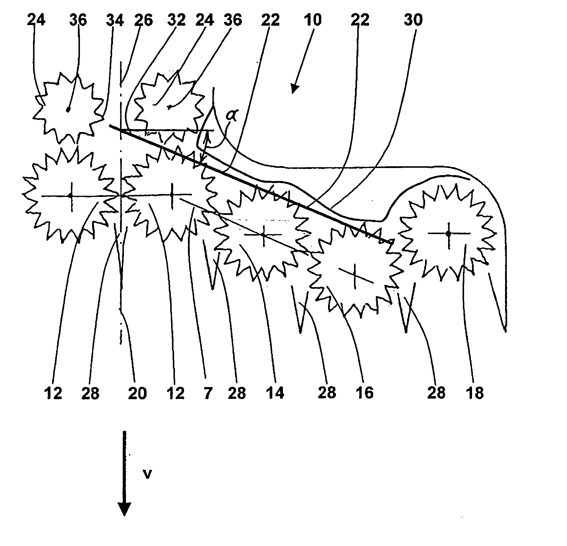
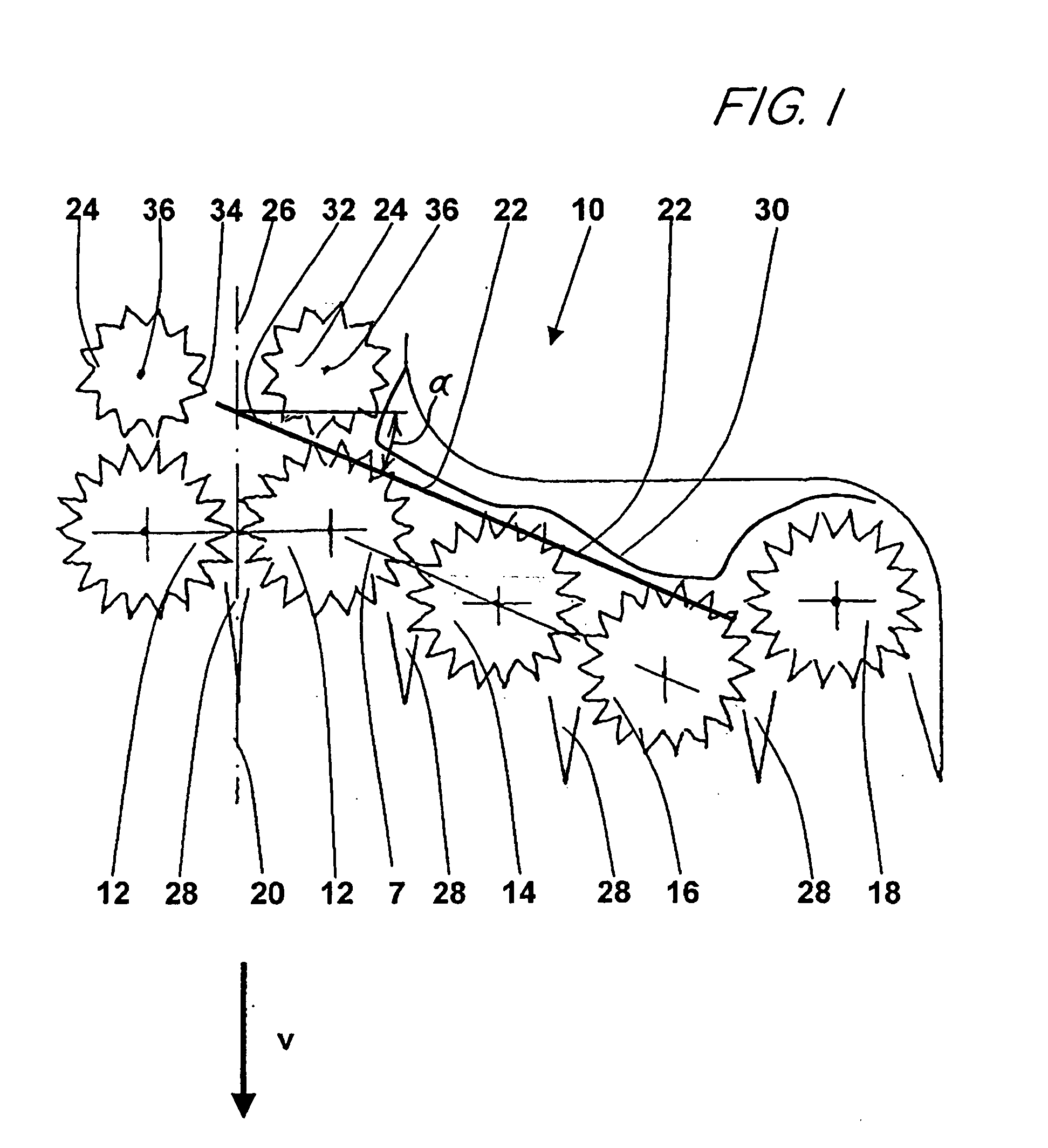
[0020]FIG. 1 shows a schematic top view of half of a first embodiment of a header 10 of the invention for mowing stalk crops, for example, corn. It comprises several mowing and feed devices 12, 14, 16, 18, which are equipped in a manner known per se with cutting disks rotating around a vertical axis and conveyor disks disposed above these, with notches distributed around their periphery to take up the stems of the cut plants. Mowing and feed devices 12-18 of this type are disclosed in detail in EP 0 099 527 A, the content of which is incorporated into the present documents by reference.

[0021] In FIG. 1, to simplify the description, only the half of the header 10 on the left side of the longitudinal mid-plane 20 of the header 10, relative to the forward direction V in which the header 10 moves over a field for harvesting, and the inner part of the right half are shown completely. The right half, however, in reality is a mirror image to the left half. The header 10 accordingly has ei...


PUM


Abstract

A header for mowing stalk crops is equipped with several mowing and feed devices which are disposed on both sides of the longitudinal mid-plane of the header. Along the backs of the mowing and feed devices at each side of the header there is a transverse conveyor channel through which plants, harvested by the mowing and feed devices, are conveyed to the center of the header. At the center of the header deflecting conveying elements are disposed on both sides in front of a feed channel of a forage harvester and operate to deflect the plants to the rear so as to transfer them to the feed channel. The transverse conveying channels are disposed at an angle relative to the transverse direction. Preferably, an extension of an imaginary line lying along the transverse conveying channel at each side of the header intersects the opposite deflecting conveying elements at or behind a point where the deflecting conveying elements move to a greater extent rearward than toward the longitudinal mid-plane of the header.

Description

FIELD OF THE INVENTION [0001] The invention relates to a header for mowing stalk crops with several mowing and feed devices which are disposed on both sides of the longitudinal mid-plane and at the backs of which there is a transverse conveyor channel, through which the plants, harvested by the mowing and feed devices, are conveyed to the center of the header, in which they are deflected rearward by means of deflecting conveying elements, disposed on both sides ahead of a feed channel of a forage harvester, and transferred to the feed channel. BACKGROUND OF THE INVENTION [0002] Headers of the aforesaid type are used in agriculture to cut stalk crops, for example, corn plants, from the soil of a field and to convey them to a harvester carrying the header. The harvester includes a chopper drum for chopping the plants into pieces which are discharged into a loading container on a trailer. Headers of this type usually have several mowing and feed devices, arranged laterally adjacent to ...

Claims


Application Information

Patent Timeline
Patent Type & Authority Applications(United States)
IPC IPC(8): A01D43/08
CPCA01D43/082
Inventor RESING, ALFONS
Owner MASCHFAB KEMPER
Why Eureka
Try Eureka