Image reading and recording apparatus

a technology for reading and recording apparatus, applied in the direction of electrical apparatus, typewriters, printing, etc., can solve the problems of reducing the speed of the scanner unit, reducing the size of the main body of the apparatus, and unable to obtain a unit, so as to reduce the opening force and the effect of sufficient buffering

Inactive Publication Date: 2010-03-23
CANON KK
View PDF4 Cites 4 Cited by
  • Summary
  • Abstract
  • Description
  • Claims
  • Application Information

AI Technical Summary

Benefits of technology

[0016]It is an object of the present invention to provide an image reading and recording apparatus capable of obtaining a sufficient buffering effect at the time of opening and closing independently of the weight of a scanner unit. Moreover, it is another object of the present invention to provide an image reading and recording apparatus capable of obtaining the function of locking a scanner unit at a closed position, the assist function of reducing an opening force, the function of holding the scanner unit at an opened position, and the buffering function at the time of closing.
[0017]It is a further object of the present invention to provide an image reading and recording apparatus including: a recording unit; a scanner unit rotatable to the recording unit; a damper unit disposed between the recording unit and the scanner unit, the damper unit including a holder coupled to the recording unit, a rod movable to the holder in an expansion and contraction direction, and a spring mounted between the holder and the rod to produce a spring force in a direction of pushing out the rod, wherein an operating direction of the spring switches while the scanner unit moves from an opened position thereof to a closed position thereof to the recording unit; a projection disposed on the rod; and a guiding surface disposed on the recording unit to abut against the projection, wherein the projection abuts against the guiding surface before the operation direction of the spring switches in process of a scanner unit's movement from the opened position thereof to the closed position thereof.

Problems solved by technology

However, if these mechanisms are separately included, then the enlargement of the apparatus main body in size and an increase in cost owing to the increase of the number of parts are brought about.
That is, the buffering effect sufficient for fully decreasing the speed of the scanner unit at the time of closing the scanner unit cannot be obtained, and the scanner unit ends up colliding with the recording unit at a considerable speed.
Consequently, it has been difficult to reduce or avoid the shock at the closed position.
In such a situation, there is a disadvantage that a user gets his or her hand stuck in the scanner unit 103 or that the apparatus is damaged by the vigorous moving of the scanner unit 103 up to the closed position thereof.
Moreover, if another buffering unit for buffering the movement of the scanner unit 103 before the closed position thereof is provided in order to avoid the disadvantage like this, then there arises the disadvantage that enlargement in size of the apparatus main body and the increase in cost of the apparatus are bring about.

Method used


Image

  • Image reading and recording apparatus
  • Image reading and recording apparatus
  • Image reading and recording apparatus

Examples


Embodiment Construction

[0029]In the following, an exemplary embodiment of the present invention will be concretely described with reference to the attached drawings. Incidentally, the same marks indicate the same or corresponding parts in common to all drawings.

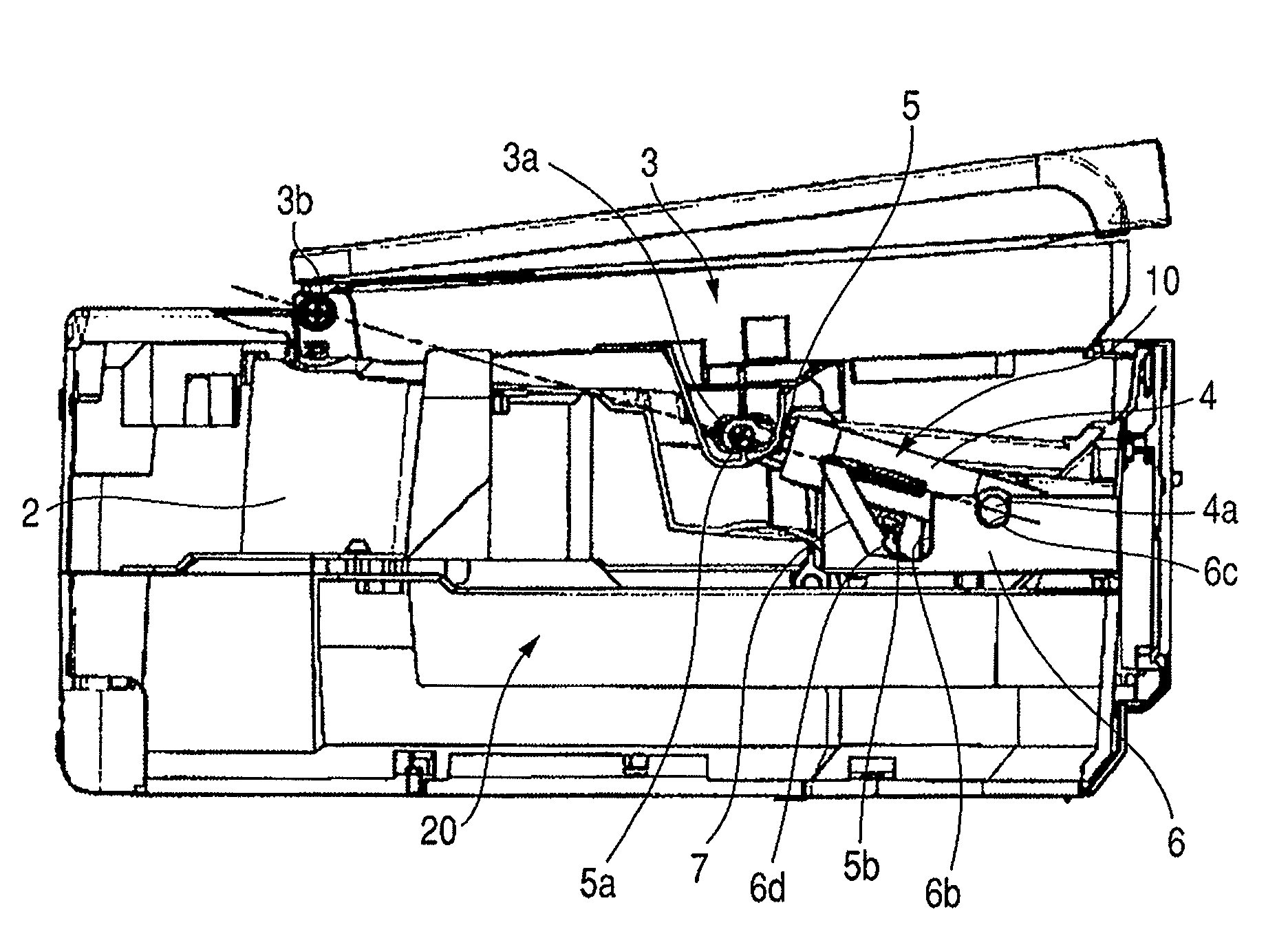
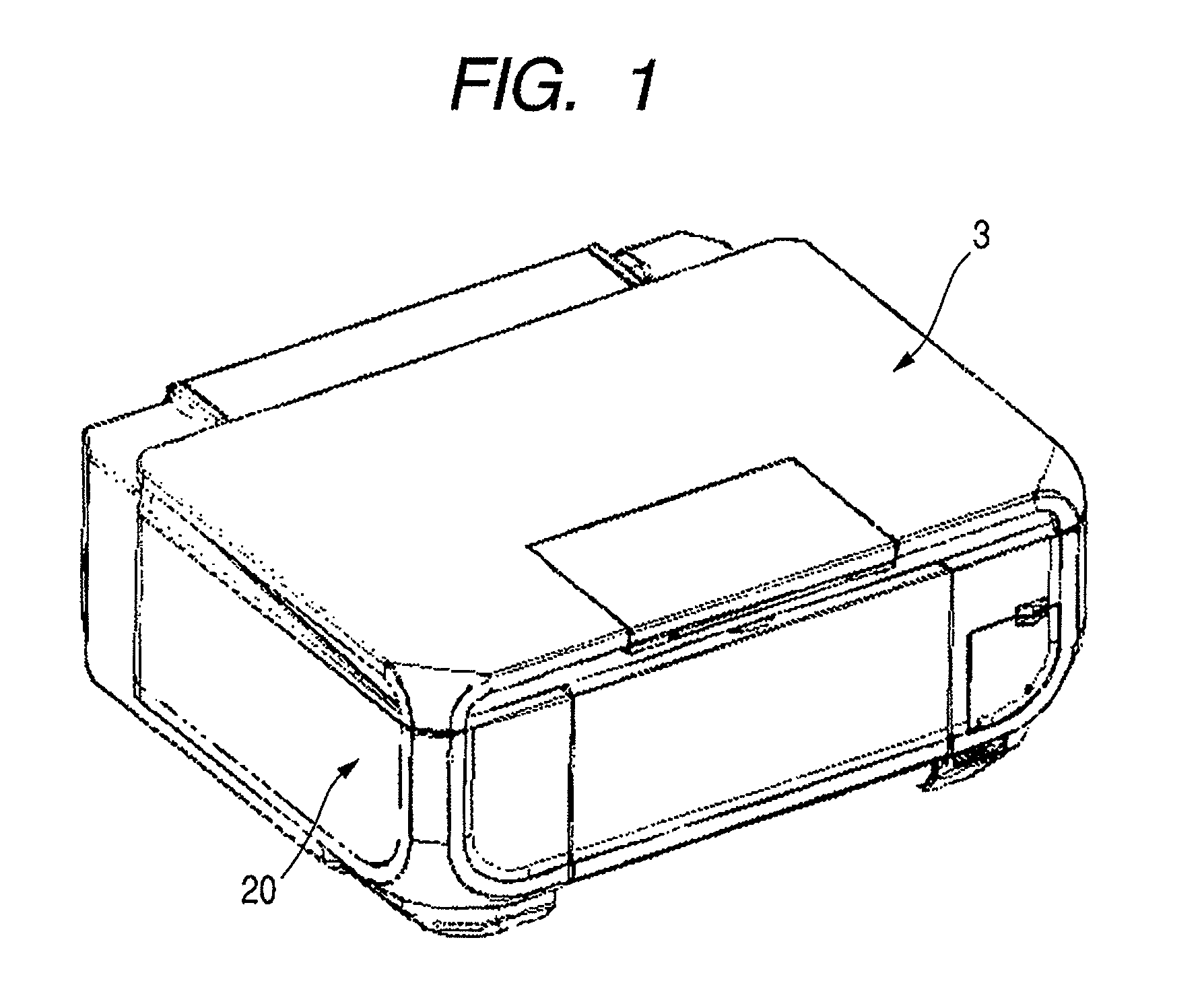
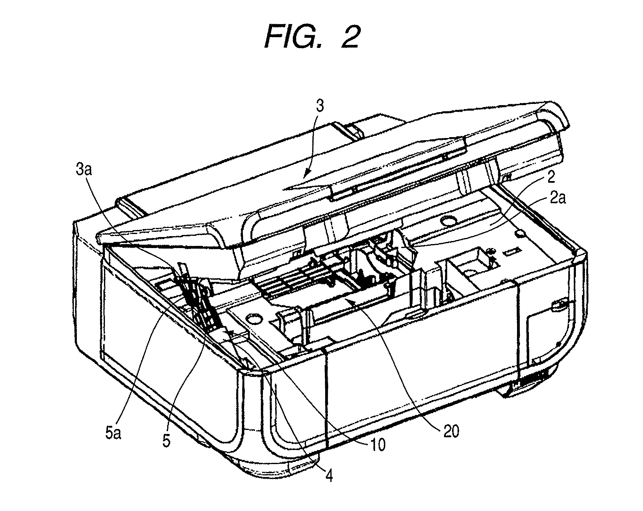
[0030]In FIGS. 1, 2, 3, 4, 5 and 6, an image reading and recording apparatus includes a recording unit 20, a scanner unit 3 attached to the recording unit 20 in a rotatable state, and a damper unit 10 coupled between the recording unit 20 and the scanner unit 3. The recording unit 20 is composed of a recording apparatus recording an image on a recording material, such as recording paper, with a recording head based on image information, for example. The scanner unit 3 constitutes a cover unit for closing an opened portion 2a (see FIG. 2) for the maintenance of the recording unit 20. The scanner unit 3 reads an image of an original with a reading unit such as a CCD.

[0031]The upper part of the recording unit 20 is composed of a housing-like frame 2. ...


PUM


Abstract

A scanner unit is revolvable disposed to a recording unit. The recording unit and the scanner unit are coupled with each other with a damper unit including a holder, a rod, and a spring. The damper unit is disposed so that the operating direction of the spring switches in process of the opening and the closing of the scanner unit. A guiding surface capable of abutting on the projection disposed on the rod is provided in the recording unit. The projection abuts on the guiding surface before the operating direction of the spring switches in process of the movement of the scanner unit from its opened position to its closed position.

Description

BACKGROUND OF THE INVENTION[0001]1. Field of the Invention[0002]The present invention relates to an image reading and recording apparatus composed of combining a recording unit and a scanner unit, and more particularly to a mechanism for opening and closing a scanner unit to a recording unit.[0003]2. Description of the Related Art[0004]There has been conventionally an image reading and recording apparatus composed of combining a recording apparatus and a scanner. The recording apparatus here records an image onto a recording material with a recording head based on image information. The scanner reads an image on an original with a reading unit, such as a CCD, and outputs the read image signal. An image reading and recording apparatus is generally adapted to mount a scanner unit on a recording unit, which is a recording apparatus, in the state capable of opening and closing the scanner unit. The image reading and recording apparatus is adapted to move the scanner unit upward for main...

Claims


Application Information

Patent Timeline
Patent Type & Authority Patents(United States)
IPC IPC(8): B41J23/00
CPCH04N1/00543H04N1/00554H04N1/00562
Inventor SAITO, TETSUYAYOKOMIZO, ATSUSHI
Owner CANON KK
Why Eureka
Try Eureka