Process to minimize turbine airfoil downstream shock induced flowfield disturbance

a turbine and airfoil technology, applied in the direction of wind motors with parallel air flow, wind motors with perpendicular air flow, liquid fuel engine components, etc., can solve the problems of unsteady pressure variations on downstream airfoils, flow angle variations, adversely affecting both the mechanical integrity of the affected airfoils, etc., to reduce static pressure and reduce the unsteady variation

Inactive Publication Date: 2010-03-30
HONEYWELL INT INC
View PDF15 Cites 8 Cited by
  • Summary
  • Abstract
  • Description
  • Claims
  • Application Information

AI Technical Summary

Benefits of technology

[0005]The present invention includes a process of designing transonic airfoils to minimize downstream shock and, more particularly, to reduce the unsteady variation in static pressure and flow angle at downstream airfoils.
[0007]In another exemplary embodiment, a method of designing adjacent transonic airfoils to minimize downstream shock induced flowfield disturbance, in which each transonic airfoil includes at least two adjacent airfoils, a suction surface and a pressure surface coupled together via a leading edge and a trailing edge, and each airfoil is spaced apart from its adjacent airfoils to define an airfoil passage therebetween includes the steps of determining a cross passage shock location on each airfoil suction surface. The cross passage shock location corresponds to a location off of which a shock that emanates from an adjacent airfoil trailing edge pressure surface reflects. Each airfoil suction surface is provided with a concentrated convex curvature at the cross passage shock location.

Problems solved by technology

The generated shock waves may propagate downstream and cause unsteady pressure variations on downstream airfoils and / or flow angle variations at the inlet to downstream airfoils.
These unsteady pressure variations and flow angle variations can adversely impact both the performance and the mechanical integrity of the affected airfoils.

Method used


Image

  • Process to minimize turbine airfoil downstream shock induced flowfield disturbance
  • Process to minimize turbine airfoil downstream shock induced flowfield disturbance
  • Process to minimize turbine airfoil downstream shock induced flowfield disturbance

Examples


Embodiment Construction

[0026]Before proceeding with the detailed description, it is to be appreciated that the described embodiment is not limited to use in conjunction with a particular type of turbine engine. Thus, although the present embodiment is, for convenience of explanation, depicted and described as being implemented in a multi-spool turbofan gas turbine jet engine, it will be appreciated that it can be implemented in various other types of turbines, and in various other systems and environments.

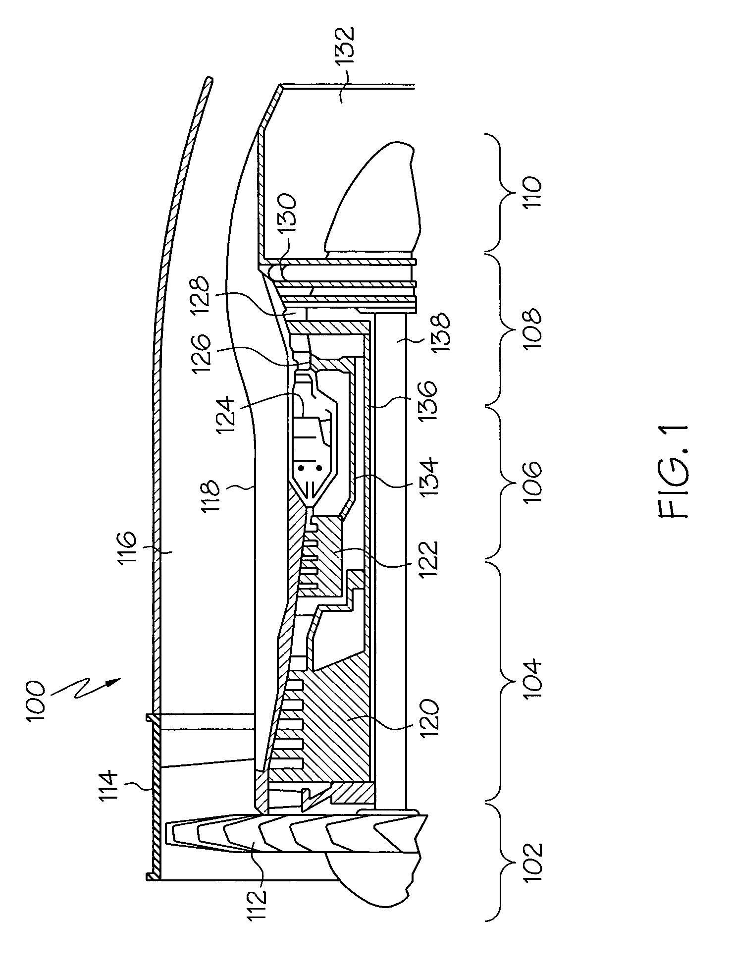
[0027]An exemplary embodiment of a multi-spool turbofan gas turbine jet engine 100 is depicted in FIG. 1, and includes an intake section 102, a compressor section 104, a combustion section 106, a turbine section 108, and an exhaust section 110. The intake section 102 includes a fan 112, which is mounted in a fan case 114. The fan 112 draws air into the intake section 102 and accelerates it. A fraction of the accelerated air exhausted from the fan 112 is directed through a bypass section 116 disposed betw...


PUM

PropertyMeasurementUnit
exit deviation angleaaaaaaaaaa
deviation angleaaaaaaaaaa

Abstract

A process of designing a transonic airfoil that results in an exit deviation angle that is optimized to minimize downstream shock induced flowfield disturbances. Specifically, a design process of a transonic airfoil minimizes pitchwise variation in downstream static pressure that includes determining an airfoil exit deviation angle and downstream turning for reduced shock from a trailing edge of the transonic airfoil.

Description

TECHNICAL FIELD[0001]The present invention relates to an airfoil design for use in a turbine and, more particularly, to an airfoil design that minimizes downstream shock induced flowfield disturbances.BACKGROUND[0002]Many aircraft include one or more gas turbine engines. The gas turbine engines may be used to provide propulsion, electrical power, and / or bleed air. In efforts to reduce the cost and weight of aircraft gas turbine engines, there recently has been a drive toward high-work turbine stages. The airfoils in high-work turbine stages typically operate in transonic conditions. That is, the airfoils typically operate in conditions where the Mach number in the relative frame of the airfoil exceeds 1.0 over some portion of the airfoil surface.[0003]When turbine airfoils operate in transonic conditions, shock waves may be generated at the trailing edge of the airfoils. The generated shock waves may propagate downstream and cause unsteady pressure variations on downstream airfoils ...

Claims


Application Information

Patent Timeline
Patent Type & Authority Patents(United States)
IPC IPC(8): B21D53/78B21K25/00B63H1/26F01D1/02F03B1/00
CPCG06F17/5095F05D2240/302Y10T29/49336Y10T29/4932Y10T29/49316Y02T50/673G06F30/15Y02T50/60Y02T90/00
Inventor MCKEEVER, CRAIG W.
Owner HONEYWELL INT INC
Why Eureka
Try Eureka